Page 5
LonTalk Zone Sensor Installed:
1. Set ECTO 6.01 to option 3 (zone sensor system mode
with return air temperature back−up).
2. Set ECTO 6.17 to option 1 (continuous blower during
occupied).
3. Set ECTO 5.27 to option 2 (network zone sensor op-
tion).
IMC Settings:
1. Be sure the occupied 24 VAC input is energized by
adding a jumper wire between TB1−8 and 9. In the
event that communication is lost between the LonTalk
module and the IMC, the IMC will operate in the occu-
pied mode and use the occupied backup setpoints.
2. Change IMC UNIT ADDRESS DIP switch to 2 (see fig-
ure 7).
0
2
0
0
+0
=2
1
2
4
8
16
SET THE ADDRESS DIP
SWITCH TO 2
Figure 7. Address DIP Switch
Settings: M2 Controllers
On the M2 Unit Controller, select SETTINGS > CONTROL
> L CONN as shown in the following diagram; default set-
ting for ADDR (address) is 2. Confirm the address and
change if necessary.
L CONN
ADDR:02
CONTROL
SETTINGS
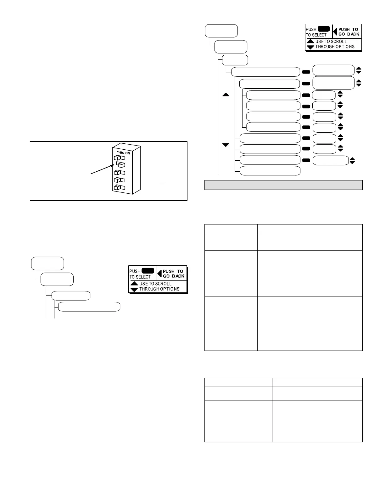
On the M2 Unit Controller, select SETTINGS > CONTROL
> LONTALK as shown in the following diagram; default set-
tings will be used. You may adjust those settings to suit the
building’s requirements. The following diagram shows the
LONTALK menu’s structure and how to make changes.
Use arrows to move
CONTROL MODE
BACKUP SENSOR
OCP HEAT BU STPT 70.0ºF
UNOCP HEAT BU STPT 60.0ºF
OCP COOL BU STPT 75.0ºF
UNOCP COOL BU STPT 85.0ºF
STARTUP DELAY (2 − 30) 2 MIN
OVERRIDE TIMER (0 8HR) 1 HR
BLOWER ON OCP
NETWORK COMFORT SENSOR
LONTALK
CONTROL
CYCLES OR
CONTINUOUS
1. NO BACKUP
2. TSTAT
3. RET AIR SENSOR
MONITOR ONLY
ZONE
SETTINGS
Communication Check−Out
LonTalk Module Communication
Use the following table as a guide once the controller and
LonTalk Module are connected and powered (LEDs are
shown in Details A and B in figure 6).
LED Action
BUS and XMIT
LEDs flash.
None. Indicates normal communica-
tion.
BUS and XMIT
LEDs are off.
1−Check cable connection between the
modules.
2−Reverse polarity of the cable between
the and LonTalk Module.
3−Check 24VAC power to LonTalk mod-
ule.
BUS LED flashes
but XMIT LED is
off.
1−Make sure unit address is set to 2.
2−Make sure MODE DIP RECALL
switch is OFF. (M1 controllers only)
3−Make sure MODE DIP ECTO switch
is OFF. (M1 controllers only)
4−Make sure MODE DIP UNIT TEST
switch is OFF. (M1 controllers only)
LonWorks Network Communication
Use the following table as a guide once the LonWorks net-
work is set up and operating.
LED Action
LonWorks communica-
tion LEDs L1 & L3 flash.
None.
Indicates normal communication.
LonWorks communica-
tion LED L1 & L3 are off.
1−Check LonWorks network con-
nections.
2−Make sure LonWorks network is
commissioned.
3−Make sure 24 volts is con-
nected to the LonWorks module.
 Loading...
