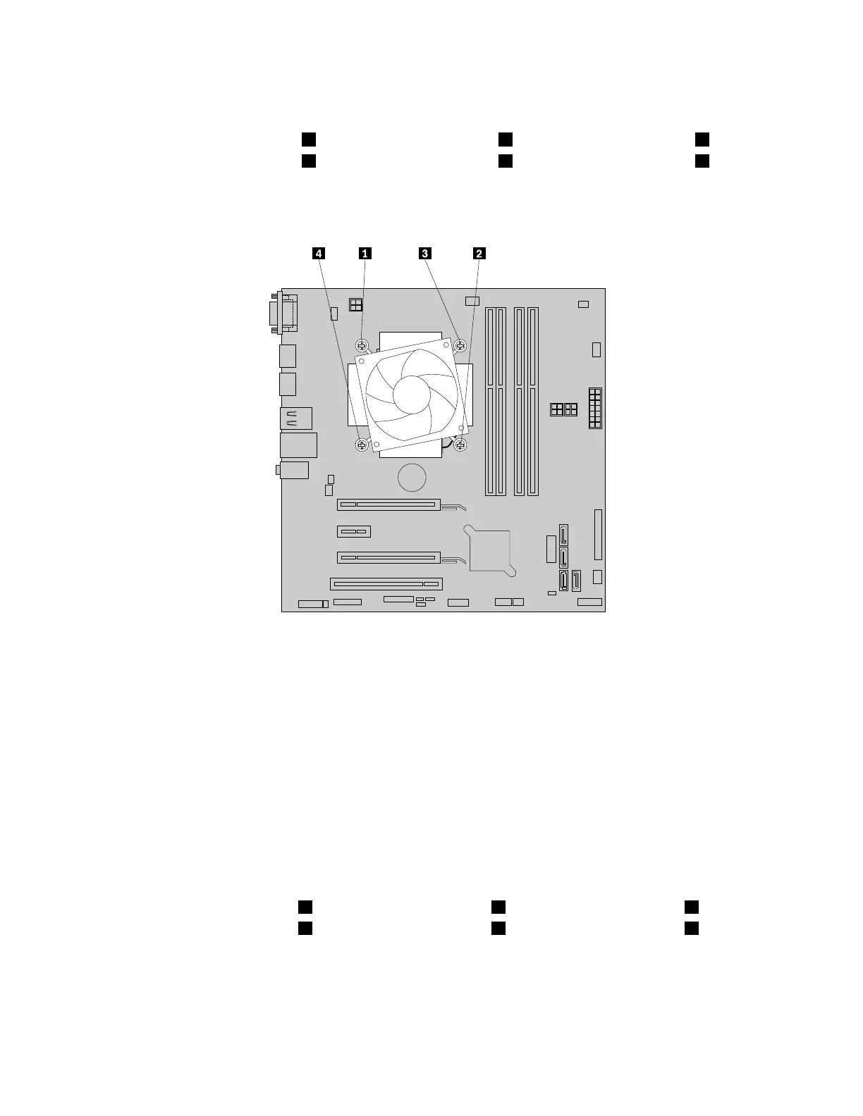
7.Followthefollowingsequencetoremovethefourscrewsthatsecuretheheatsinkandfanassembly
tothesystemboard:
a.Partiallyremovethescrew1,thenfullyremovethescrew2,thenfullyremovethescrew1.
b.Partiallyremovethescrew3,thenfullyremovethescrew4,thenfullyremovethescrew3.
Note:Carefullyremovethefourscrewsfromthesystemboardtoavoidanypossibledamagetothe
systemboard.Thefourscrewscannotberemovedfromtheheatsinkandfanassembly.
Figure61.Removingtheheatsinkandfanassembly
8.Lifttheheatsinkandfanassemblyoffthesystemboard.
Notes:
•Youmighthavetogentlytwisttheheatsinkandfanassemblytofreeitfromthemicroprocessor.
•Donottouchthethermalgreasewhilehandlingtheheatsinkandfanassembly.
9.Positionthenewheatsinkandfanassemblyonthesystemboardsothatthefourscrewsonthenew
heatsinkandfanassemblyarealignedwiththecorrespondingholesonthesystemboard.Ensurethat
thecableofthenewheatsinkandfanassemblyfacestowardthemicroprocessorfanconnector
onthesystemboard.
10.Followthefollowingsequencetoinstallthefourscrewstosecurethenewheatsinkandfanassembly.
Donotover-tightenthescrews.
Notes:
a.Partiallytightenthescrew1,thenfullytightenthescrew2,thenfullytightenthescrew1.
b.Partiallytightenthescrew3,thenfullytightenthescrew4,thenfullytightenthescrew3.
72ThinkCentreM83,M93/pUserGuide
 Loading...