Basics for wiring according to EMC
Installation in the control cabinet
6
Basic unit wiring
6.3
6.3.3
L
6.3-5
EDS82EV903-1.0-11/2002
Separation of the“hot” motor cable from control cables, signal cables and mains
cables:
l Never lay motor cables and signal cables in parallel. Crossings must be
layed at right angles.
l The cables of a 24V mains supply (positive and negative cable) must be
routed together over the total length.
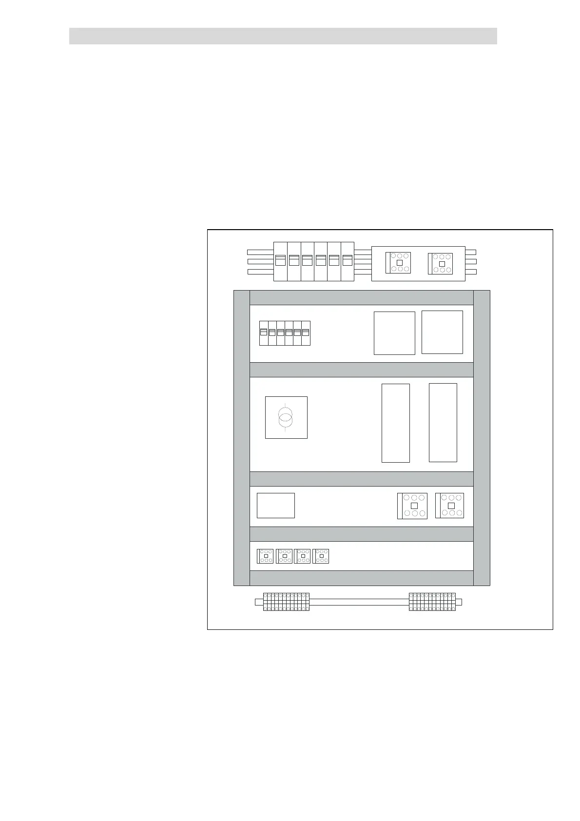
Mains
filter
Mains
filter
8200
vector
8200
vector
PLC
Mains fuses
Fuses
24V power supply unit
Motor
contactor
Relay
Terminals
Cable duct for signal cables and mains cables
ble
ct f
r
t
r c
ble
Fig. 6.3-3 Cable routing in the control cabinet
Continuation of cable routing
Mains contactors