Configuration of analog and digital setpoints and actual values
Digital setpoints via frequency input
10
Function library
10.8
10.8.4
L
10.8-12
EDS82EV903-1.0-11/2002
1. Link UP and DOWN with external signal sources: C04110/7 UP and
C0410/8 DOWN
)
))
) Note!
In addition to the free configuration under C0410 you can also use
the fixed assignment under C0007 to combine the function with
digital inputs.
2. Assign the signal source ”Motor potentiometer” to the required setpoint
under C0412 (C0412/x = 3). (¶ 10.12-1)
Function
UP DOWN
Decelerate setpoint to 0 Hz along QSP ramp LOW LOW
Decelerate t he setpoint along the main setpoint ramp
(C0013) to minimum output frequency (C0010)
(Setpoint must have been higher than value set under
C0010)
LOW HIGH
Accelerate the setpoint along the main setpoint
acceleration ra mp (C0012) to maximum o utput fre quency
(C0011)
HIGH LOW
Setpoint remains constant HIGH HIGH
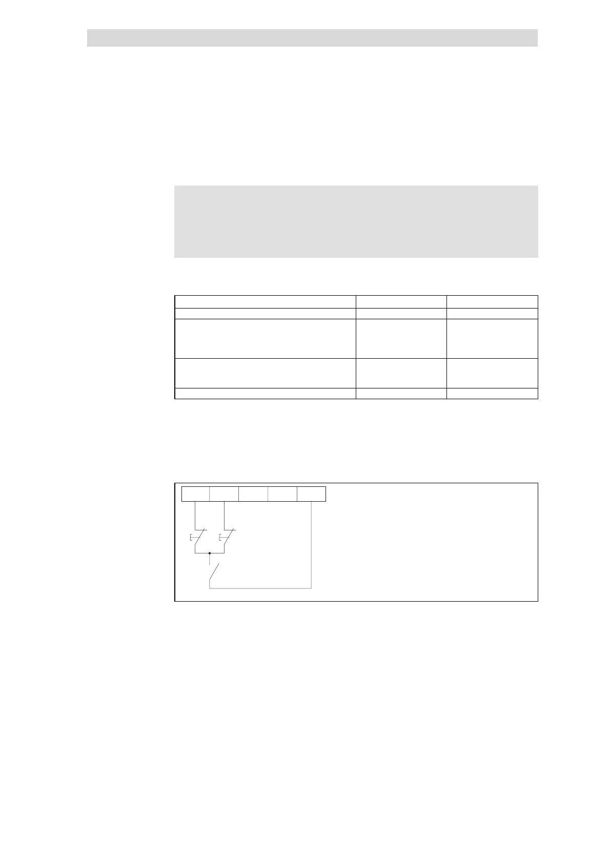
Example:Activation of the function“Motor potentiometer”via NC contacts
Configuration
E1 = ”UP”: C0410/7 = 1
E2 = ”DOWN”: C0410/8 = 2
E1 E2 E3 E4 20
Fig. 10.8-5 Motor potentiometer with NC contacts
Activation
Example
 Loading...