Pressure control
15
Application examples
15.2
L
15.2-3
EDS82EV903-1.0-11/2002
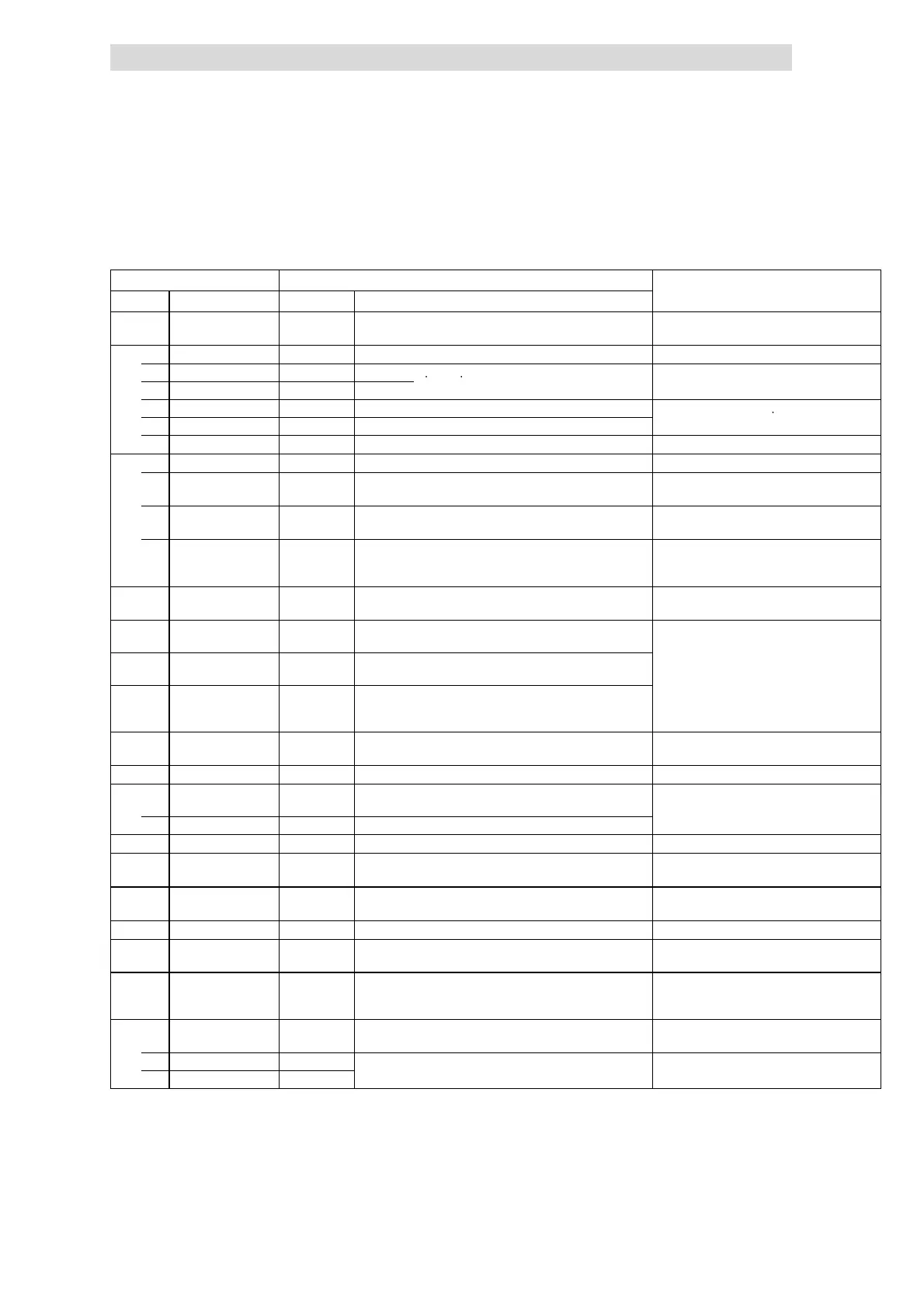
Application-specific configuration
l
Motor parameter identification. (¶ 10.9-1)
Code Settings IMPORTANT
No. Name Value Meaning
C0014 Operating mode 3 V/f characteristic control V ~ f Square-law characteristic with constant V
min
boost
C0410 Digital signals source
8 DOWN 1 E1
Inputs of pushbuttons “UP” and “DOWN”
7 UP 2 E2
1 JOG1/3 3 E3 JOG speed for night reduction
Activation of the JOG speed deactivates the
19 PCTRL1-OFF 3 E3 Process controller deactivation
process controller.
17 M/Re 4 E4 Changeover PLC/setting up operation at site
C0412 Analog signal source
1 Setpoint 1
(NSET1-N1)
1 X3/2I Pressure setpoint (manual)
2 Setpoint 2
(NSET1-N2)
3 MPOT1-OUT Motor potentiometer function Pressure setpoint (remote)
5 Act. process
controller value
(PCTRL1-ACT)
4 X3/1U Actual pressure value
C0145 Process controller
setpoint source
0 Total setpoint (PCTRL1-SET3) Main setpoint + additional setpoint
C0070 Process controller
gain
à
If necessary, adapt to process
à More information: ^ 10.10-1 ff.
C0071 Process controller
readjust me nt time
à
C0072 Differential
component of
process controller
à
C0074 Process controller
influence
100.0 0.0 {0.1 %} 100.0
C0238 Frequency precontrol -0- -0- No precontrol (only process controller) Process controller has full influence
C0419 Free configuration of
analog outputs
Analog signal source
1 X3/62 (AOUT1-IN) 8 Actual process controller value
C0037 JOG1 17 Derating to approx. 1/3 of rated motor speed
C0239 Minimum frequency
limitation
10.00 Setpoint-independent minimum speed
C0182 Integration time
S-ramps
0.50 s Smooth start
C0625 Skip frequency 1 30.00 Hz
C0628 Bandwidth of skip
frequencies
10.00 % ref. t o C0625
C0119 Configuration PTC
input/earth fault
detection
4 PTC input active, TRIP set
C0415 Free configuration of
digital outputs
1 Relay output K1 16 Ready for operation
2 Digital output X3/A1 25 Trip error message
 Loading...