9
Electrical installaon
Operang Instrucons i550-Cabinet
5 Electricalinstallaon
5.1 Generaloverviewoftheconnecons
The connecon diagram is considered exemplary for all voltage and power classes. Deviang
mains connecon diagrams can be found in the corresponding chapters.
X1
SIA
GS
SIB
DC 24 V SELV/PELV
(+19.2 … +28.8 V)
"
1k ... 10k
0 ... 10 V
S1
DI3 DI4
100 mA
4.4k
+24 V +10 V
4.4k
4.4k
4.4k
4.4k
10 mA
GND
DO1
DI1
DI2
DI3
DI4
DI5
24E
GND
AI1
AI2
10V
GND
AO1
24V
24E
X3
X105
U
V
W
Rb1
Rb2
+
X109
T1
T2
""
M
3~
+
J
J
NC
NO
COM
X9
AC 240 V
3 A
+
F1
Q1
X100
L1
L2/N
1/N/PE
AC 170 V ... 264 V
45 Hz ... 65 Hz
E
N
3/N/PE
AC 400 V
L3
Motor connecon
PTC or
thermal
contact
Safety STO
Control terminals
Mains connecon
Relay output
5.2 EMC-compliantinstallaon
The drive system (inverter and drive) meet the EMC Direcve 2014/30/EU if they are instal-
led according to the guidelines of CE-typical drive systems.
The structure in the control cabinet must support the EMC-compliant installaon with shiel-
ded motor cables.
• Please use suciently conducve shield connecons.
• Connect the housing with shielding eect to the grounded mounng plate with a surface
as large as possible, e. g. of inverters and RFI lters.
• Use central earthing points.
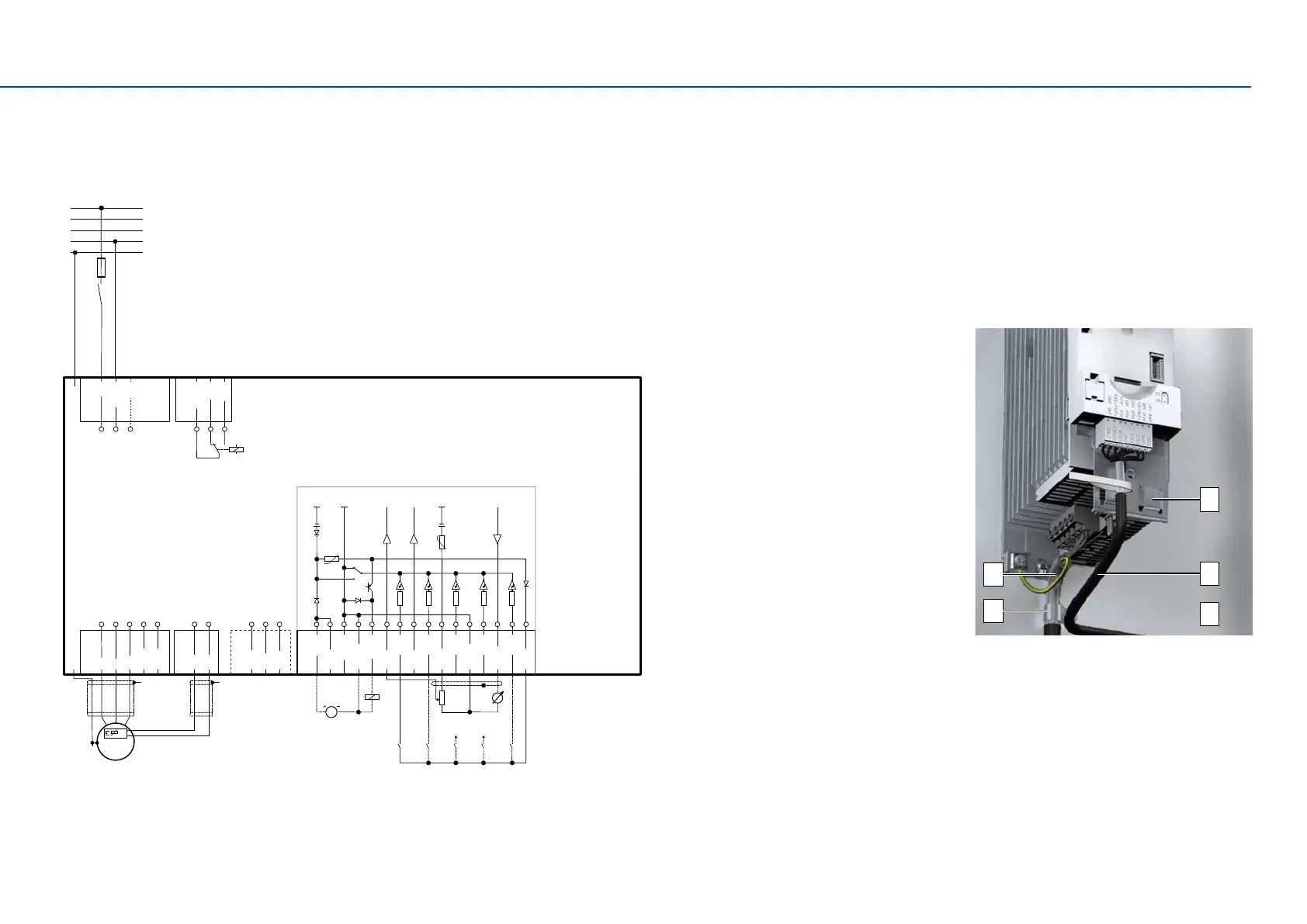
The following gure shows an eecve wiring with shielding on the control cabinet wall.
A Shield connecon for control connecons
E
C
B
D
A
B Control cable
C Electrically conducve mounng plate
D Shield clamps
E Low-capacitance motor cable
(C-core/core/C-core/shield
< 75/150 pF/m ≤ 2.5 mm²;
C-core/core/C-core/shield
< 150/300 pF/m ≥ 4 mm²)
Alternavely, the motor cable can be shielded on an oponal motor shield plate.

 Loading...


