21
Commissioning
Operang Instrucons i550-Cabinet
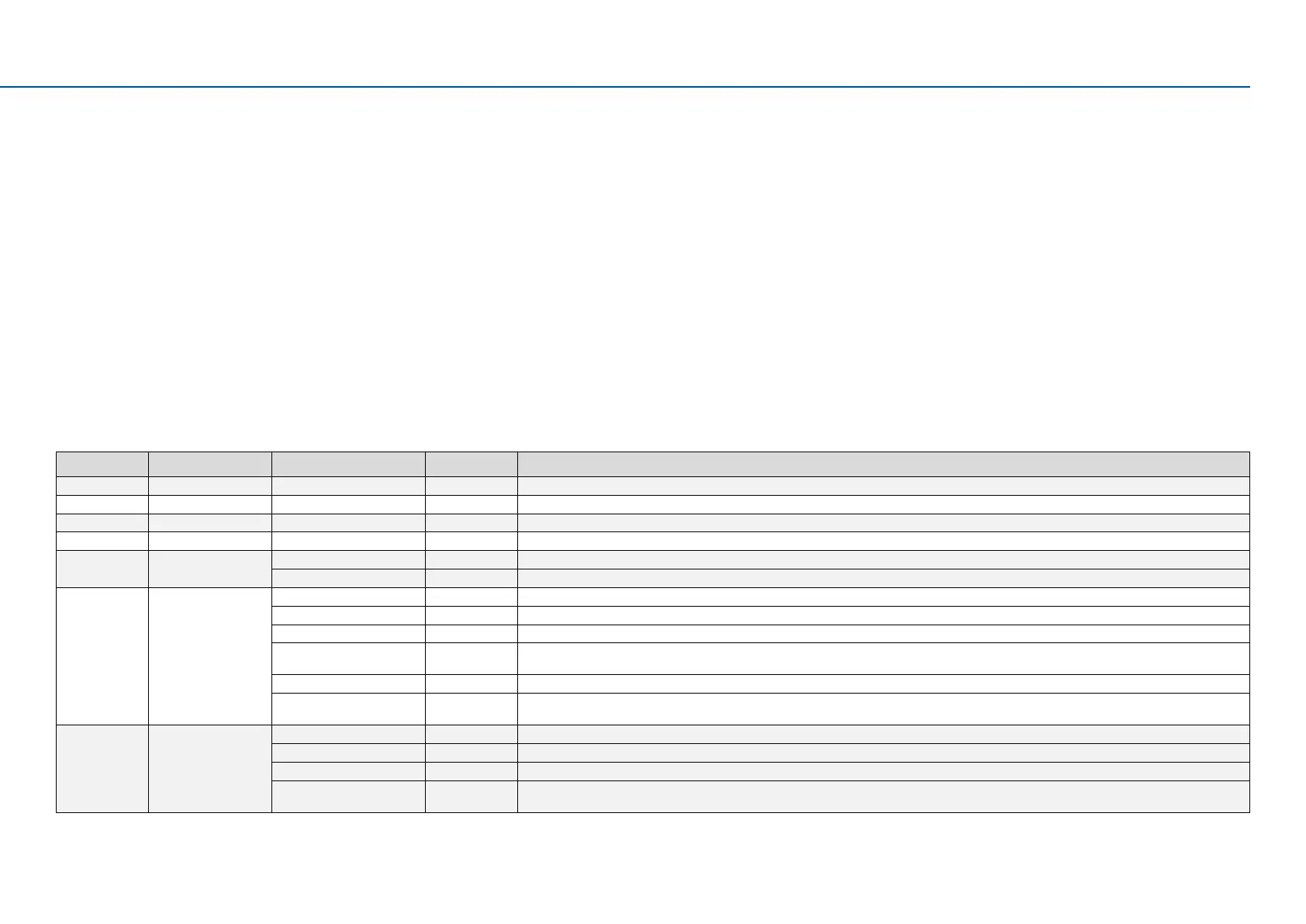
7.4 The most important parameters at a glance
This chapter contains the most important parameters and selecons. You can nd a detailed descripon in the commissioning document. hp://www.Lenze.com
The parameters are divided into the following funcon groups:
• Pxxx.xx group 0: Favorites
• P1xx.xx group 1: Diagnoscs
• P2xx.xx group 2: Basic seng
• P3xx.xx group 3: Motor control
• P4xx.xx group 4: I/O seng
• P5xx.xx group 5: Network seng
• P6xx.xx group 6: Process controller
• P7xx.xx group 7: Addional funcons
• P8xx.xx group 8: Sequencer
7.4.1 Group 0: Favorites
Group 0 contains the congurable favorites that are also contained in the groups 1 to 8. In the default seng these are the most common parameters for the soluon of typical applicaons.
Display code Designaon Possiblesengs/valueranges Keypad code Informaon
P100.00 Output frequency x.x Hz (read only) Display of the actual output frequency.
P103.00 Current actual x.x % (read only) Display of the actual motor current.
P106.00 Motor voltage x VAC (read only) Display of the actual motor voltage.
P150.00 Error code - (read only) Error message.
P200.00 Control selecon Flexible I/O [0] This selecon enables a exible assignment of the start, stop, and rotang direcon commands with digital signal sources.
Keypad [1] This selecon enables
the motor to start exclusively via the start key of the keypad. Other signal sources for starng the motor are ignored.
P201.01 F-setp.source Keypad [1] The setpoint is specied locally by the keypad.
Analog input 1 [2] The setpoint is dened as analog signal via the analog input 1.
Analog input 2 [3] The setpoint is dened as analog signal via the analog input 2.
HTL input [4] The digital inputs DI3 and DI4 can be congured as HTL input to use an HTL encoder as setpoint encoder or dene the setpoint as a reference
frequency ("pulse train").
Network [5] The setpoint is dened as process data object via the network.
Frequency preset 1 ... 15 [11] ... [25] For the setpoint selecon, “preset” values can be parameterized and selected. All frequency presets are described in detail in the
commissioning manual. hp://www.Lenze.com
P203.01 Start method Normal [0] Aer start command, the standard ramps are acve.
DC braking [1] Aer start command, the "DC braking" funcon is acve for the me set in P704.02.
Flying restart circuit [2] Aer the start command, the ying restart circuit is acve.
Premagnezaon [3] Aer start command, the standard ramps are acve and the premagnezaon of the motor is acvated. This reduces the motor current and smoothes the
acceleraon curve during the starng process (only relevant in the V/f motor control mode).

 Loading...


