26
Commissioning
Operang Instrucons i550-Cabinet
7.4.2 Group2:Basicseng
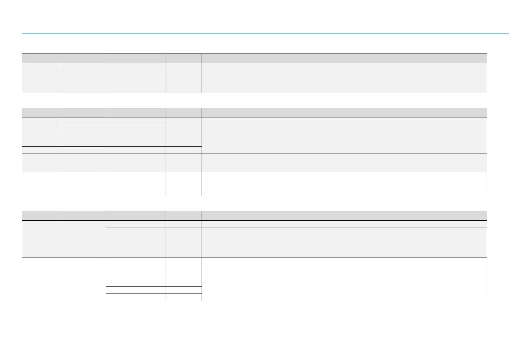
Display code Designaon Possiblesengs Keypad code Informaon
P225.00 Quick stop decelera-
on me
1.0 s Quick stop deceleraon me for “MS: Velocity mode”
• If the "Quick stop" funcon is acvated, the motor is brought to a standsll within the deceleraon me set here.
• The deceleraon me set refers to the deceleraon from the maximum frequency set (P211.00) to standsll. In the case of a lower actual
frequency, the actual deceleraon me is reduced accordingly.
• Seng is not eecve in the operang mode P301.00 = “CiA:Velocity mode”.
7.4.3 Group 3: Motor control
Display code Designaon Possiblesengs Keypad code Informaon
P320.04 Rated speed 50 ... 50000 rpm General motor data.
Carry out sengs as specied by motor nameplate data.
Note!
When you enter the motor nameplate data, take into account the phase
connecon implemented for the motor (star or delta connecon). Only
enter the data applying to the connecon type selected.
P320.05 Rated frequency 1.0 ... 10000.0 Hz
P320.06 Rated power 0.00 ... 655.35 kW
P320.07 Rated voltage 0...65535V
P320.08 Cos phi 0.00 ... 1.00
P327.04 Idenfy motor data 0 ... 1 1 = start automac idencaon of the motor data.
• Inverter characteriscs, motor equivalent circuit diagram data and controller sengs are idened and set automacally.
• During the procedure, the motor is energized!
P327.05 Calibrate motor data
(non-energized)
0 ... 1 1 = start automac calibraon of the motor data.
• A default inverter characterisc is loaded.
• The motor equivalent circuit diagram data and controller sengs are calculated on the basis of the currently set rated motor data.
• The motor is not energized.
7.4.4 Group7:Addionalfuncons
Display code Designaon Possiblesengs Keypad code Informaon
P700.01 Device commands:
Load default sengs
O/ready [0] Only status feedback
On / start [1] 1 = reset all parameters in the RAM memory of the inverter to the default seng that is stored in the inverter rmware.
• All parameter changes made by the user are lost during this process!
• This process may take some seconds. When the device command has been executed successfully, the value 0 is shown.
• Loading parameters has a direct eect on cyclic communicaon: The data exchange for control is interrupted and a communicaon error is
generated.
P700.03 Save USER data O / ready [0] 1 = save current parameter sengs in the user memory of the memory module with mains failure protecon.
• It may take some seconds to execute the task. When the device command has been executed successfully, the value 0 is shown.
• Do not switch o the supply voltage during the saving process and do not unplug the memory module from the inverter!
• When the inverter is switched on, all parameters are automacally loaded from the user memory of the memory module to the RAM
memory of the inverter.
On / start [1]
In progress [2]
Acon cancelled [3]
No access [4]
No access (Inverter disabled) [5]

 Loading...


