4. Operation DA2DVI-DL – User's Manual 10
4
Operation
This chapter is about the powering and operating of the device describing the
Î
Î
are powered down before connecting them. Powered on devices may
have dangerous voltage levels that can damage sensitive electronic
circuits.
the unit and then to the power outlet. The unit is immediately powered
ON.
Step 1.
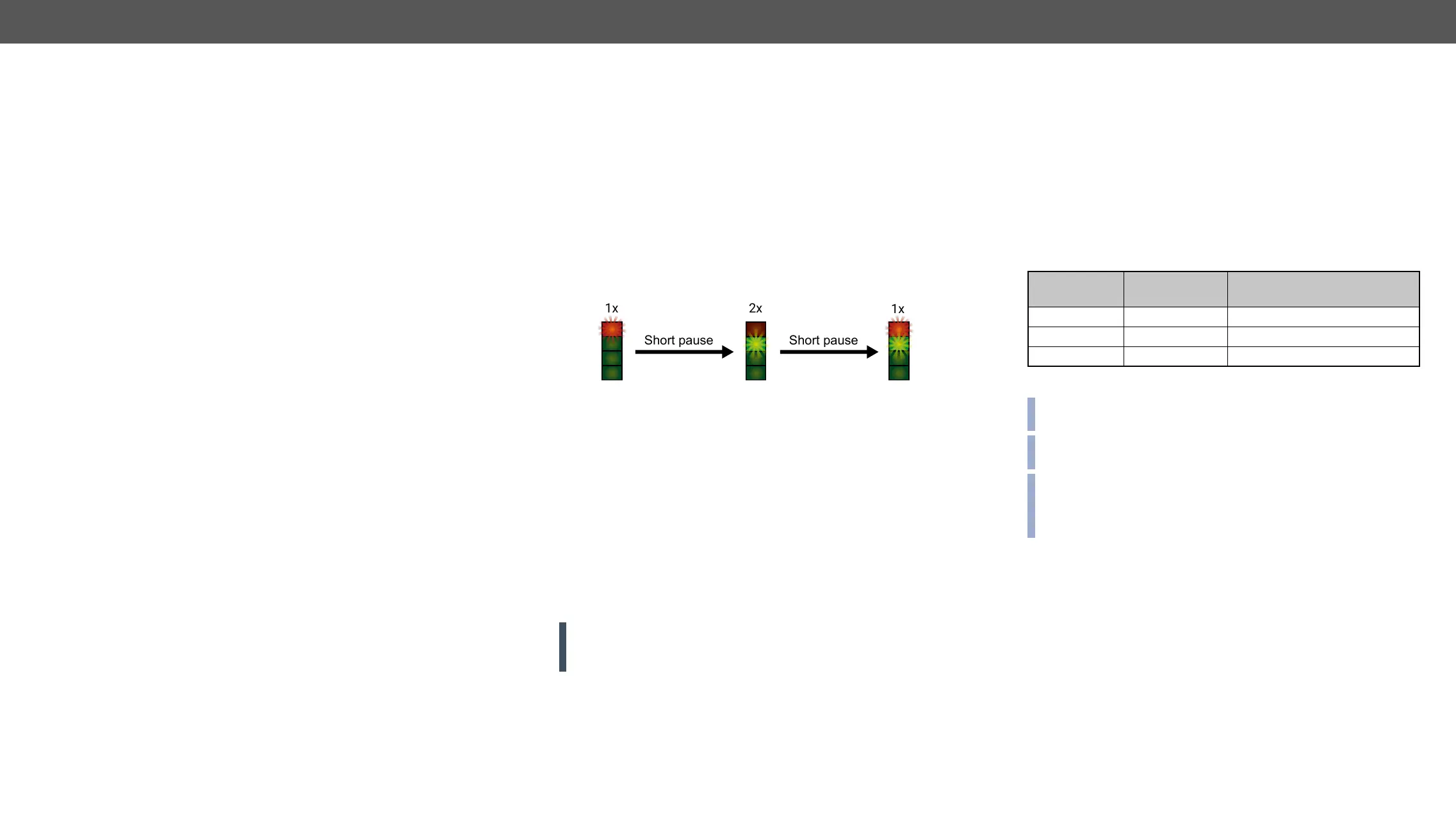
version using the EDID Status LEDs. The following example
Step 2. EDID
Status LED lights up depending on the selected EDID’s validity:
– Red – ‘N’: the selected EDID is invalid.
– Green – ‘Y’: the selected EDID is valid
Step 3. If a display device is connected to DVI-DL OUTPUT 1, the
DA2DVI-DL reads the EDID from the attached monitor’s EDID
memory.
– If the read process is successful, the STATUS LED blinks
green four times.
– If the read process is unsuccessful, the STATUS LED blinks
red four times.
Step 4. The normal function of the LEDs is in effect.
WARNING! If none of the LEDs light up upon power-up, the unit is
-
tact support@lightware.eu.
Short pause
Short pause
EDID Operations
About EDID memory
Lightware factory preloaded EDIDs are specially provided to force
graphic cards to output only the exact pixel resolution and refresh rate.
Universal EDID (address 49#) allows multiple resolutions including all
support. The use of universal EDID is advised for fast and easy system
setup.
DA2DVI-DL contains a 79 block non-volatile memory bank. EDID
memory is structured as follows:
Rotary switch
state
Memory bank
number
Factory Preset EDID list
U01..U29 User programmable slots
#00 D01 Last attached monitor’s EDID
Factory EDID list can be found in Factory EDID List section.
the most commonly used resolutions.
extended EDID structures.
INFO: The attached monitor’s EDID is stored automatically, until a
new monitor is connected to the OUTPUTs. In case of powering the
unit off, the last attached monitor’s EDID remains in non-volatile
memory.
 Loading...