3. Product Overview DA2DVI-DL – User's Manual 9
Electrical Connections
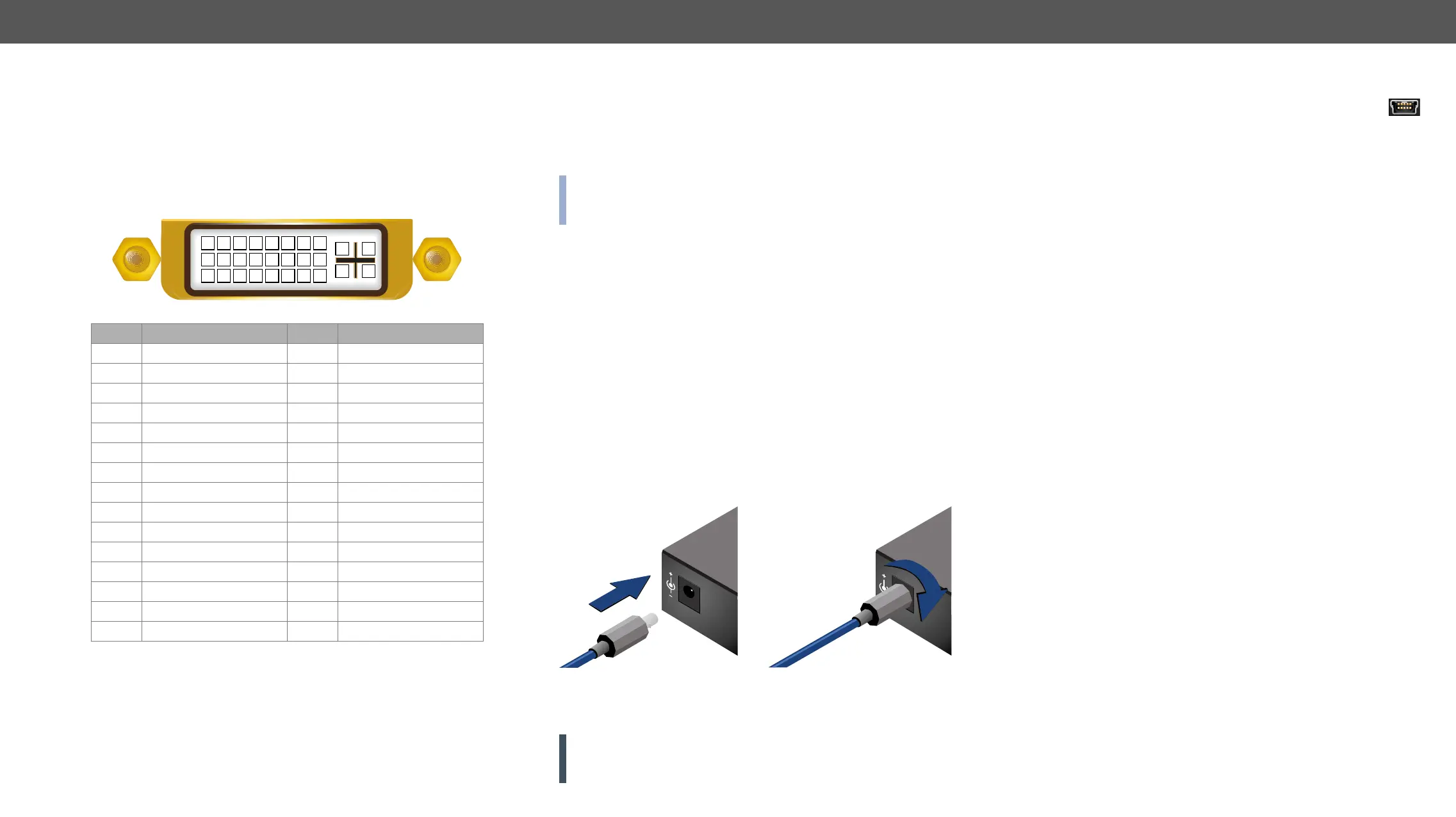
DVI-I Connector
DA2DVI-DL provides 29 pole „digital only” DVI-I Dual-Link connectors
(only digital pins are internally connected). This way, users can plug in
any DVI connector, but keep in mind that analog signals (such as VGA
or RGBHV) are not processed.
Always use high quality DVI cable for connecting sources and displays.
Signal Signal
1 TMDS Data2- 16 Hot Plug Detect
2 TMDS Data2+ 17 TMDS Data0-
3 4 Shield 18 TMDS Data0+
4 TMDS Data4- 19 8 Shield
5 TMDS Data4+ 20
6 DDC Clock 21
7 DDC Data 22 TMDS Clock Shield
8 not connected 23 TMDS Clock+
9 TMDS Data1- 24 TMDS Clock-
10 TMDS Data1+ C1 not connected
11 3 Shield C2 not connected
12 TMDS Data3- C3 not connected
13 TMDS Data3+ C4 not connected
14 C5 GND
15
DVI-DL Output
Monitor hotplug is detected on the DVI-DL OUTPUT 1 (HPD LED lights
green). After a hotplug event, the DA2DVI-DL tries to read the EDID of
the connected device.
No output reclocking is provided. If a long DVI cable is connected then
the cable.
1 2 3 4 5 6 7 8
9 10 11 12 13 14 15 16
C1 C2
C4C3
C5
17 18 19 20 21 22 23 24
optical DVI transmitters. Standard DVI outputs or VGA cards supply
optical cable.
INFO: The device does not check if the connected sink (monitor,
projector or other equipment) supports hotplug or EDID signals but
outputs the input signal directly.
DVI-DL Input
The input has Dual-Link disable option, which ensures Single-Link
compatibility. Devices supporting Dual-Link output can confuse
Single-Link inputs; disabling the Dual-Link TMDS channel distribution
solves this problem. For more information see Output Port Properties
section.
Cable length at inputs
please use one of our cable extender solutions, for example the
Lightware DVIDL-Extender.
DC 5V Connection
The device has a locking DC connector to establish robust and safe
power connection. After plugging it in, turn the plug clockwise as you
can see in the picture below.
Locking DC connector
Do not forget to turn the plug clockwise direction before disconnecting
the power adaptor.
WARNING! Always use the supplied 5V power adaptor or Light-
ware’s rack mountable power supply. Warranty void if damage oc-
curs due to use of a different power source.
12V 1A
5V 1A
PIN: 2.35mm
PIN: 2.35mm
USB Connector
The device provides standard USB 2.0 mini B-type connector
Software Control –
Lightware Device Controller and in Programmer's Reference chapters.
Firmware
Upgrade chapter.
 Loading...