3. Product Overview DA2DVI-DL – User's Manual 8
3
Product Overview
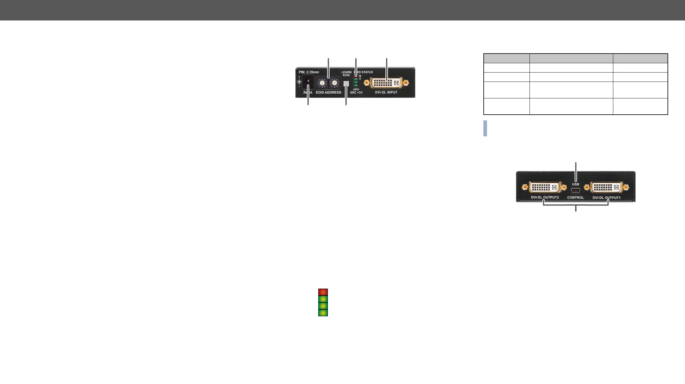
output ports and connectors:
Î
Î
Î
1
DC 5V
input
adaptor or use Lightware’s rack mountable power
supply unit. See more information in the
Connection section.
2
Rotary
switches
The rotary switches select one of the EDID
memory addresses. See more information in the
EDID Operations section.
3
Learn
button
Stores the EDID of the display device attached
to DVI-DL OUTPUT 1 in the selected memory
see the Learning the EDID section.
4
Status
LEDs
Display EDID information during operation and
boot up. See the details below.
5
DVI-DL
input
Connect one single or dual-link DVI cable (only
digital pins are connected internally) between the
DVI source and DA2DVI-DL. See more information
in the DVI-I Connector section.
Status LEDs
1
2
3
4 5
EDID status Y (green)
HPD (green)
The LEDs display basic information about EDID and connected
devices’ status:
LED label LED is illumenated LED is blinking
EDID STATUS N Selected EDID is invalid EDID learn failure
EDID STATUS Y Selected EDID is valid EDID learn success
HPD
Hotplug detect: OUTPUT 1 is
connected
-
on INPUT
-
described in the Powering On section.
Rear View
1
USB control Advanced EDID management and
USB interface.
2
DVI-DL outputs Connect single or dual-link DVI cables
(only digital pins are connected
internally) between DA2DVI-DL and the
display devices. The output connectors
more information in the DVI-I Connector
section.
1
2
 Loading...