- 47 -
9LD Workshop Manual _ cod. 1.5302.286 - 3° ed_rev. 02
4
91
92
90
Disassembly / Reassembly
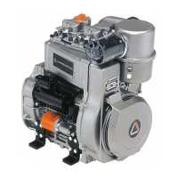
Valve timing - Angles
The angle values are determined by turning the driving shaft clockwise
S =Piston at top dead centre
I =Piston at bottom dead centre
αα
αα
α =Intake valve open
ββ
ββ
β =Intake valve closed
γγ
γγ
γ =Exhaust valve open
δδ
δδ
δ =Exhaust valve closed
Timing angles for checking puposes
(valve clearance = 0,65÷0,70 mm)
αα
αα
α =1° before S
ββ
ββ
β =21° after I
γγ
γγ
γ =23° before I
δδ
δδ
δ =1° after S
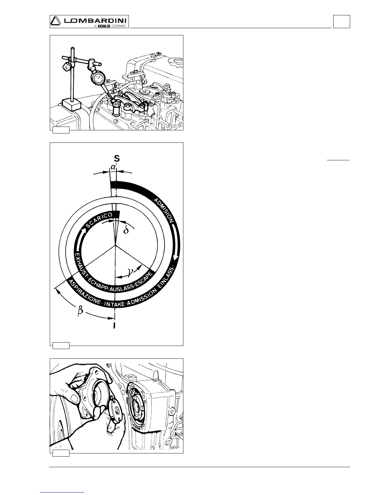
HYDRAULIC PUMP
Hydraulic pump p.t.o
A hydraulic pump of group 1 (1P) or 2 (2P) can be installed on the gear
side, 3rd p.t.o.
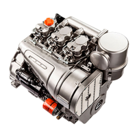
Valve timing check
Check valve timing at the crankshaft.
The values shown are checked at the flywheel circumference (with
flywheel of 291 mm. diameter each degree corresponds to 2.5 mm).
Set valve clearance at 0.65÷0.70 mm (after checking restore the value
at 0.15÷0.20 mm).
Set dial gauge on intake valve to a zero value; by rotating the driving
shaft according to its direction of rotation you can measure
αα
αα
α (intake
valve opening advance referred to top dead centre S) and ß (intake valve
closing delay referred to bottom (I) dead centre).
Follow the same procedure for exhaust valves checking
γγ
γγ
γ (exhaust valve
opening advance) and
δδ
δδ
δ (exhaust valve closing delay).
 Loading...