- 74 -
9LD Workshop Manual _ cod. 1.5302.286 - 3° ed_rev. 02
7
168
169
V21V42
V21V82
A14A31
1
2
3
V21V42
V21V42
A04A02
A36.0A03.0
8
6
7
4
9
10
3
2
5
1
Electric System
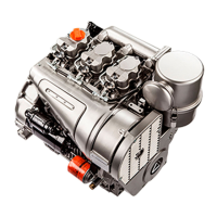
Pre-heating glow plug
Components: 1 Sheath
2 Regulation filament
3 Heating filament
When remounting tighten at a torque of 20 Nm.
Note: The glow plug is not damaged in any way due to the prolonged
activation time.
Nominal voltage
Current
Glow plug Type
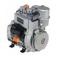
DIRECT STOP ELECTROMAGNETS
Reverse electromagnet – FIRE version
Features:
Components:
1 Nut
2 Stud bolt
3 Flat washer
4 Screw
5 Spacer
6 Spherical joint
7 Electromagnet
8 Stop control lever
9 Axial joint
10 Stop control electromagnet support
Adjustment:
-Carry out the adjustments by screwing and unscrewing the joints.
-Adjust the device so as to make the electromagnet get to the end of
the stroke before the STOP lever reaches its limit stop after
performing the operation stroke.
-When the electromagnet is excited, put the stop lever at about 1.0 –
1.5 mm from its limit stop.
-Once adjustment phase is completed, tighten nut 1.
Important
The control cover should not present the return spring of the
stop lever.
Remove the stop lever return spring without replacing the
control cover if the device is applied to engines that were
originally not equipped with it.
Operating tension
Power coil absorption
Electromagnet type
Hold coil absorption
 Loading...