EasyManuals Logo
Home>Makita>Impact Driver>DTD152

Makita DTD152 Technical Information

Makita DTD152
27 pages
To Next Page IconTo Next Page
To Previous Page IconTo Previous Page
Page #18 background imageLoading...
Page #18 background image
July 2015
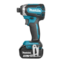
9. Hammer section (17-25) can be disassembled as shown in
the figure on the left:
- Hammer (17)
- Steel ball 3.5 (18) (x24)
- Flat washer 24 (19)
- Compression spring 25 (20)
- Spindle (23)
Figure 35
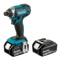
10. Remove Thin washer 15 (25) and two Pin 5 (24) from
Spindle (23).
Figure 36
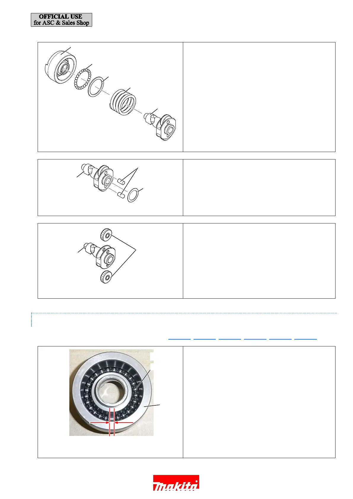
11. Remove two Spur gears 22 (22) from Spindle (23).
Figure 37
3.3.4.2. ASSEMBLING
Assemble by reversing the disassembly procedure. (See Figure 37, Figure 36, Figure 35, Figure 34, Figure 33, Figure 32)
Note in Assembling:
Before assembling Steel balls 3.5 (18), check the following
points:
(A) Twenty-four Steel balls 3.5 (18) are put in the groove of
Hammer (17) as shown in the figure on the left.
(B) There is a gap equivalent to the size of one Steel ball 3.5
(18).
Figure 38
(A)
(B)
(17)
(18)
(19)
(20)
(23)
(23)
(24)
(25)
(22)
(18)
(17)
(23)
18 / 27

Other manuals for Makita DTD152

Questions and Answers:

Question and Answer IconNeed help?

Do you have a question about the Makita DTD152 and is the answer not in the manual?

Makita DTD152 Specifications

General IconGeneral
Power sourceBattery
Battery voltage18 V
Battery level indicatorYes
Product colorBlack, Blue
Idle speed (max)3500 RPM
Screw diameter (max)16 mm
Maximum torque (hard applications)165 N⋅m
Vibration emission10.5 m/s²
Weight and Dimensions IconWeight and Dimensions
Depth137 mm
Width79 mm
Height238 mm
Weight1500 g

Related product manuals