National Crane 1-21-2019 Control # 104-07 6-9
1400A SERVICE MANUAL SWING
Torque wrenches are precision instruments and must be
handled with care. To ensure accuracy, calibrations must be
made on a scheduled basis. Whenever there is a possibility
that a torque wrench may have been either overstressed or
damaged, it should immediately be removed from service
until re-calibrated. When using a torque wrench, any erratic
or jerking motion can result in the application of excessive or
improper torque. ALWAYS use a slow, even movement and
STOP when the predetermined value has been reached.
If it is reported by the crane operator or suspected that the
crane has been overloaded beyond the capacities specified
above the bold line on the cranes’ capacity chart, then all
swing bearing bolts must be inspected for looseness and
re-torqued to specifications.
Torque the swing bearing bolts according to the procedures
outlined in this section.
When using step wrenches, calculated wrench settings are
valid only when the following conditions are met.
1. Torque wrenches must be those specified and forces
must be applied at the handle grip. The use of handle
extensions will change applied torque to the bolt.
2. All handles must be parallel to the step wrench during
final tightening. Multiplier reaction bars may be
misaligned no more than 30 degrees without causing
serious error in torque.
3. Multiplier bar handles must be propped or supported
within the outer 1/4 of the handle length, or serious
under or over tightening will occur.
Swing Bearing Bolts
The inner race of the bearing is secured to the turret by 36,
7/8 inch Grade 8 bolts (Figure 6-5). The outer race of the
bearing is secured to the carrier frame by 32, 3/4 inch, Grade
8 bolts (Figure 6-5).
Torque Values
Torque all swing bearing bolts to a final torque: Fasteners
and Torque Values on page 1-7.
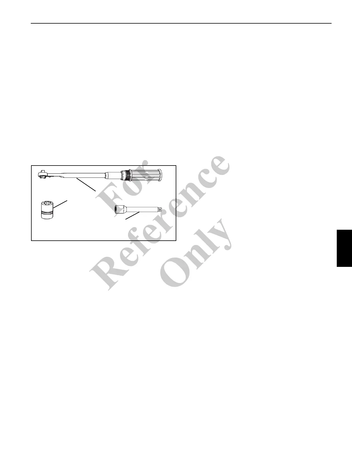
Tools Required
A complete set of special tools required to torque the swing
bearing bolts is listed and shown in (Figure 6-4).
Inner Race Torquing
The inner race bolts can be accessed through the access
holes underneath the bed (Figure 6-6).
1. Extend and set the outriggers. Fully elevate the boom.
2. Torque eight bolts (Figure 6-5) to 637 Nm ±27 Nm (470
lb-ft ± 20 lb-ft) using the following sequence pattern; 1,
19, 10, 28, 6, 23, 15, and 33. Tools used are the socket,
multiplier, backlash adapter, necessary extensions, and
torque wrench.
3. Return to bolt 1 and torque all bolts sequentially in a
clockwise direction to the final torque:
Fasteners and
Torque Values on page 1-7. The same tools are used as
in step 1.
FIGURE 6-4
Torque Wrench 3/4 inch Drive
3/4 and 7/8 inch
sockets
Extension
Fo
r
Reference
Only

 Loading...


