National Crane 1-21-2019 Control # 104-07 6-13
1400A SERVICE MANUAL SWING
13. Remove the remaining bolts and washers securing the
swing bearing outer race to the carrier.
14. Carefully lift the turret and set it on blocking that will not
allow the turret to tilt or shift. Leave the lifting device
attached.
NOTE: If the current bearing is to be reinstalled, mark the
position of the bearing on the turret before removal.
15. Remove the 36 bolts from the inner race of the turret
bearing.
16. Lift the turret off the swing bearing and set on blocking.
NOTE: The bearing weighs about 284 kg (625 lb).
Check the bearing teeth for chipping or cracking. If any
evidence of these is found, replace the bearing. Ensure the
bolt holes are free of dirt, oil, or foreign material.
Installation
NOTE: If the current bearing is reinstalled, align the
marked teeth on the swing drive pinion shaft with
the marked teeth on the bearing.
1. Using an appropriate lifting device, set the turret on the
swing bearing. If the same bearing is being used,
position it as marked prior to removal.
2. Install 36 new bolts and washers securing the bearing to
the turret. Refer to Inner Race Torquing on 9.
3. Using an appropriate lifting device, align the turret over
the carrier same position that it was before removal.
4. Carefully lower the turret into position on the bearing
plate. Be careful not to damage the swivel assembly.
5. Install all bolts and washers that are not covered by the
swing motor. Refer to Outer Race Torquing on 11.
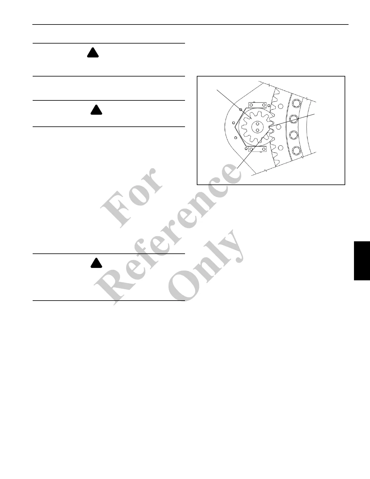
NOTE: If a new bearing is installed, a new pinion gear
must also be used. Align the high point (maximum
eccentricity) on the bearing with the high point on
the new pinion gear (Figure 6-10).
6. Install the swing drive pinion so that the high point
(maximum eccentricity) is aligned with the turret bearing
high point. Check the backlash with a 0.203 mm (0.008
in) thick shim (Figure 6-10). If the pinion must be moved
to achieve proper backlash, contact your local
distributor.
7. Plug the swivel wiring harness connectors into the
carrier receptacles.
8. Reconnect the hydraulic lines as per removal tags.
9. Install the boom and lift cylinder following the procedures
outlined in Section 4- BOOM.
10. Reconnect the batteries.
11. Carefully swing the turret so that the bolt holes that were
covered by the swing motor are accessible.
12. Install the remaining swing bearing bolts.
13. Check the slew potentiometer in the electrical swivel for
proper orientation as described below.
DANGER
Ensure the lifting device is capable of supporting the
boom assembly.
DANGER
Ensure blocking material can support the turret.
DANGER
Do not reuse the swing bearing bolts. The swing bearing
is torqued to the applied torque of the grade 8 bolts. New
bolts ensure proper torque and bolt strength for securing
the swing bearing and turret to the carrier.
0.008 Shim
Maximum
Eccentricity
Tooth
Pinion
FIGURE 6-10
Fo
r
Reference
Only

 Loading...


