HOIST SERVICE MANUAL 1400A
5-10 1-21-2019 Control # 104-07
13. Install the stator plates (19) and friction discs (18) into
the brake housing starting with a stator and alternating
friction discs and stator plates. There is one more stator
plate than friction disc so you will finish with a stator
plate.
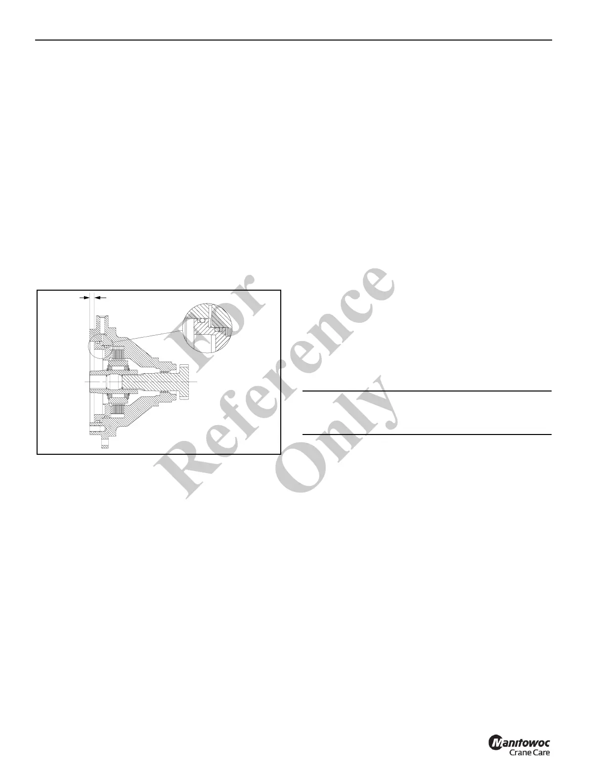
14. After installation, check the brake stackup to make sure
that the dimensions are within the tolerance shown in
Figure 5-8. If your measurement is greater than shown,
either some friction discs and stator plates have been
left out, or the friction discs are worn beyond acceptable
tolerances. If your measurement is less than shown, too
many plates or discs have been inserted or they are not
seated properly.
15. Coat the new backup rings (Items 7-7 & 7-8) and o-rings
(Items 7-1 & 7-6) with light oil and install onto the piston
(10) with the backup rings toward the outside of the
piston. See Figure 5-8 for proper o-ring and backup ring
installation.
16. Carefully install the piston into the brake housing and
gently tap it down until it is seated.
17. Install the springs (24) into the spring pockets of the
piston. If working in a horizontal position, coat the
bottom of each spring with chassis lube to keep it in
position.
18. Coat the new o-ring (7-3) with light oil and install into the
groove on the brake cover (20).
19. Install the cover (20) onto the brake housing (21) and
draw it down evenly, alternating between opposite
capscrews. Make sure that the cover is aligned
properly with the brake housing to orient the motor and
vent as they should be.
20. Check the brake release with a portable hydraulic pump.
Full release should be obtained at 250 psi, plus or minus
20 psi. Also, check the brake for proper operation by
applying 155 psi to the brake port and adapting a torque
wrench to the input shaft. The torque here in the payout
direction should be 95 to 115 lb-ft.
Planetary Set
NOTE: See Figure 5-7 for item number (#) identification.
1. Remove the spiral retaining rings (4-4, 36-4) from the
planet pins.
2. Remove the pins (4-3, 36-3) from the carrier by carefully
tapping them out.
3. Remove the planet gears, thrust washers and bearings
from the carriers.
4. Inspect the pins, bearings, and gear bores for evidence
of wear and replace if necessary.
5. On output planet sets, note that two bearings (4-6) with a
spacer (4-7) between them are used.
6. Before reassembly, be sure to insert the round plates
into the carriers (4-5, 36-5).
7. To re-assemble, be careful to line up the planet pins with
the thrust washers and bearings and then press the
knurled part of the pin into the carrier.
Motor
1. Remove the hose from the counterbalance block (12-2).
2. To remove the counterbalance block (12-2), loosen and
remove the 3 capscrews (12-3).
3. Remove the counterbalance valve (12-1) from the
counterbalance block (12-2) and inspect the small
metering hole located on the side of the cartridge valve
to make sure it is not obstructed (Figure 5-9). Also
inspect the O-rings to insure that they are not cut or
flattened.
4. Motors and cartridge valves are not serviceable in the
field. Return them to an authorized distributor for
service.
0.400 in ±0.050
(10.16 mm ±1.27)
FIGURE 5-8
CAUTION
If the pins are not lined up properly, the thrust washers
can be shattered during the pressing operation.
Fo
r
Reference
Only

 Loading...


