CRANE INSTALLATION SERVICE MANUAL 1400A
9-18 1-21-2019 Control # 104-07
Truck Interface Electrical Connection
Connections to the truck electrical system is as follows:
NOTE: Keep the harness away from the drive line and
exhaust system.
• The accessory and ignition wires are tied into the back of
the ignition switch in the truck cab.
• If there are two ignition wires when tying into the truck
ignition, tie into both wires.
• Route wires 5 & 51 to the truck battery. Be sure the wires
not pinched or cut. Cut to length and crimp on the
terminals.
• The start wire must be tied to starter solenoid on the
engine side of the firewall. Do not tie the start wire into
back of truck key switch.
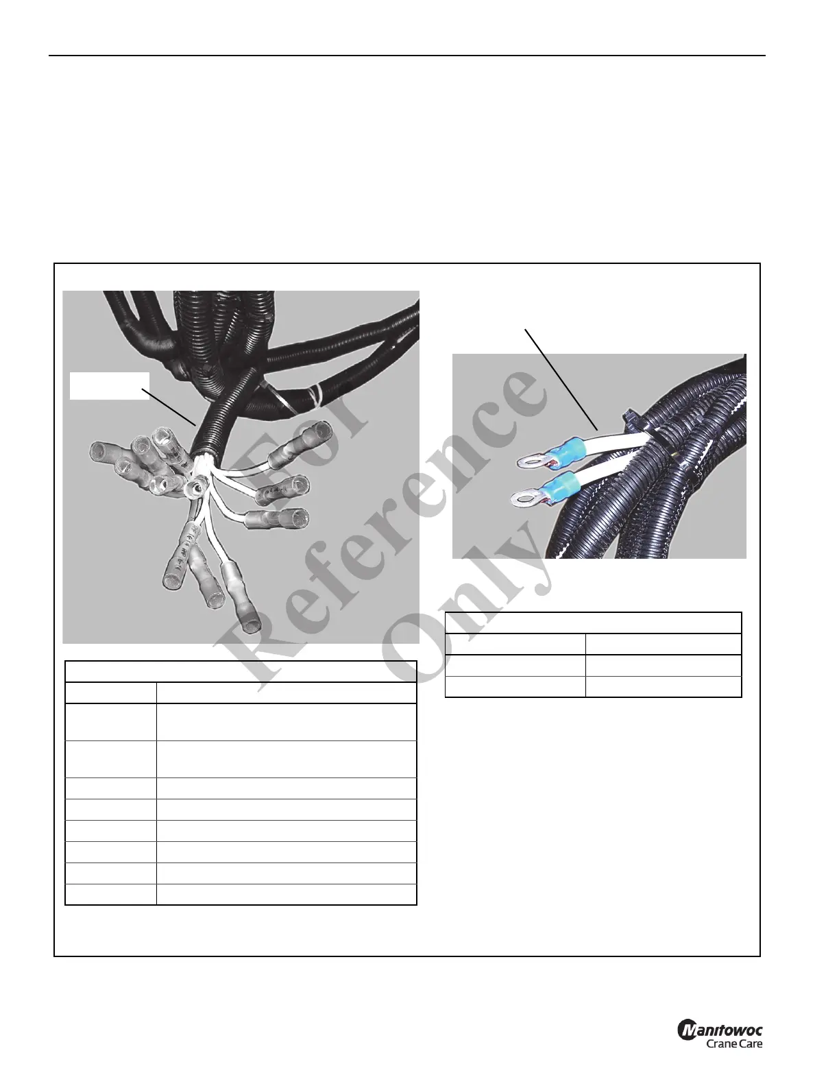
Truck Battery
Harness
Truck Interface Harness
Wire # Truck Function
473 - 475
Throttle Leads (473 - 475 for three lead
connections)
477 - 479
Throttle Leads (473 - 479 for six lead
connections)
450 Throttle Splitter Power
51 Throttle Splitter Ground
901 Ignition Switch
52 Start Switch
112 Accessory Switch
5 Auxiliary Power (Optional)
Truck Battery Harness
Wire # Truck Function
51 (-) Ground
5 (+) Positive
Truck Interface
Harness
NOTE: The type of throttle supplied with the truck
determines if three leads or six leads are
required.
Throttle Splitter Power (450) and Throttle
Splitter Ground (51) are not used when the
throttle is direct wired to the truck.
FIGURE 9-14
Fo
r
Reference
Only

 Loading...


