National Crane 1-21-2019 Control # 104-07 9-19
1400A SERVICE MANUAL CRANE INSTALLATION
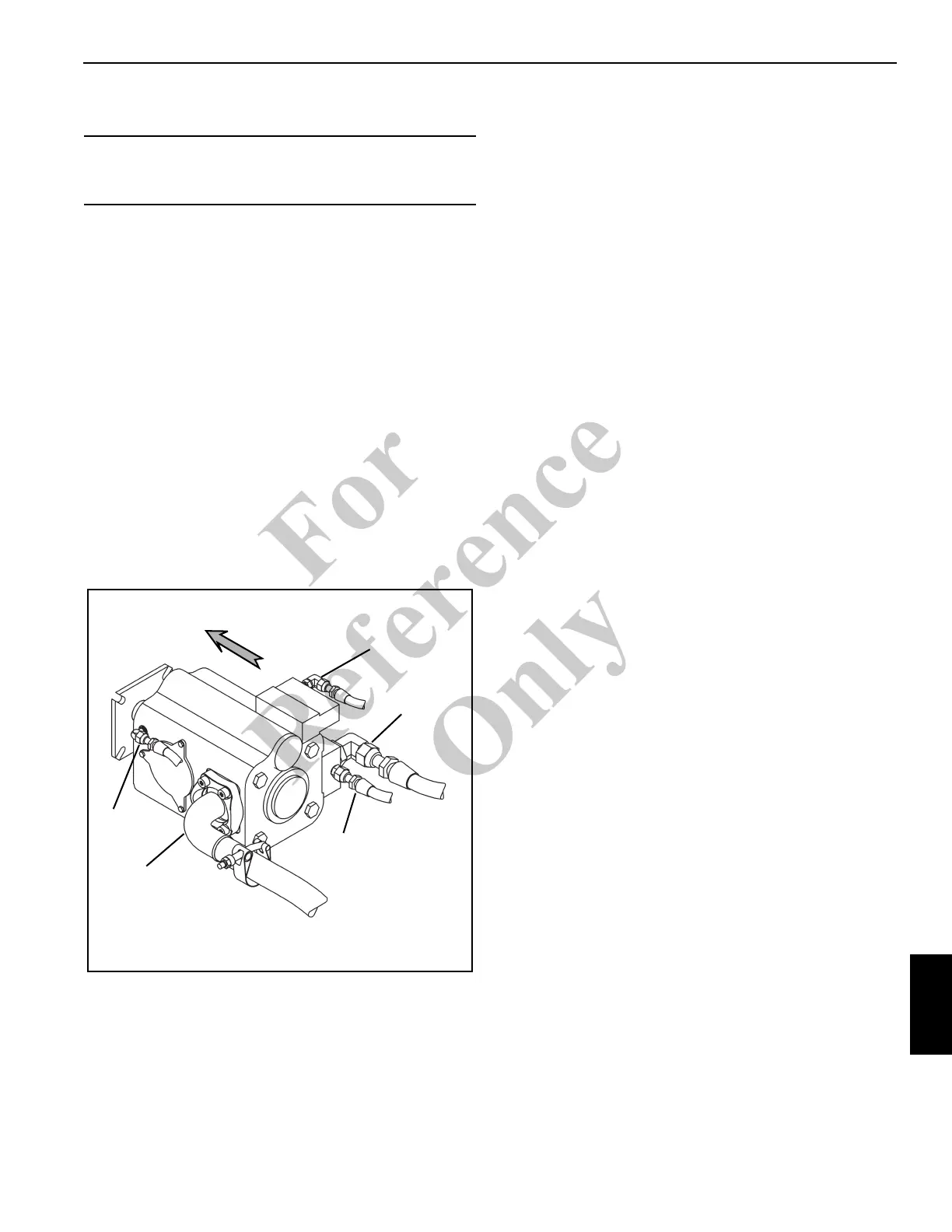
Hydraulic System Connection
The hydraulic system pressure is supplied by a hydraulic
piston pump mounted on the truck power take off (PTO). The
pump is driven counter clockwise and supplies the following
at governed rpm:
• 132 LPM (35 GPM) to the hoist
• 132 LPM (35 GPM) to the boom and telescope
• 61 LPM (16 GPM) to the turn and outrigger circuit.
Connect the hydraulic hoses to the pump sections as
marked.
12. Adjust the throttle for the engine RPM and PTO ratio to
get proper pump shaft speed.
13. Measure the overall height of the crane and truck. Post
the overall height measurement inside the truck cab to
inform the driver of the overall height.
14. The Initial Crane Run in Procedure must be completed
before the stability test is started.
RCL CALIBRATION
After the crane has been installed and all electrical and
hydraulic connections are completed, calibrate the RCL.
Calibrate the RCL as described in the RCL manual titled
Calibration/Service Manual.
INITIAL CRANE RUN IN PROCEDURE
1. Put the unit in an open area where the crane can be run
through all functions.
2. Engage the PTO and do the following:
• Start the truck engine from the crane cab.
• Program the RCL.
• Run the truck engine at idle.
• Turn the crane power switch on and operate the
crane and outriggers though all of their functions at
least six (6) times to purge the cylinders of air.
• Operate the control valves slowly with the truck
engine at idle and cycle each cylinder through its
complete stroke each time.
• Check to see that the movement of the outriggers
and boom correspond with the direction indicated
on switches and levers.
• Refer to the hydraulic and electrical sections and
hydraulic or electrical schematics in this manual.
NOTE: Add oil to reservoir as required to keep air from
reentering the system.
3. Set the throttle according to engine RPM and PTO ratio
to get the proper pump shaft speed.
4. After all the cylinders have been run through six
complete cycles, stow the crane with the outriggers
retracted. The oil level should be visible at the full mark
of the sight gage.
5. The lift and stability test must now be performed.
6. After testing is completed, check the torque on all
bearing, mounting and all cable clamp bolts.
STABILITY TEST
The purpose of the stability test is to verify that the rated load
can be lifted with an 85% tipping factor. With an 85% tipping
factor, the crane can lift a rated load and be at 85% of the
tipping condition or less.
CAUTION
Make sure the gate valve on the return line is open before
starting the pump or damage to the pump could result.
FIGURE 9-15
FRONT
To Outriggers
and Swing
Load Sense
To Hydraulic
Swivel
From Tank
Drain to
Tan k
Fo
r
Reference
Only

 Loading...


