HYDRAULIC SYSTEM SERVICE MANUAL 1400A
2-14 1-21-2019 Control # 104-07
Hydraulic Filter Replacement
The filter is mounted in the oil reservoir, and is a replaceable
element type.
The filter requires a 5 Micron replacement element. The filter
must be serviced with National Crane replacement elements
at recommended intervals to assure the warranty remains in
effect.
Element Removal
1. Shut down the hydraulic system.
2. Wipe any dirt from the filter head and cap assembly.
3. Loosen the six bolts securing the filter cap to the filter
head.
4. Twist to unlock and remove the filter cap.
5. Remove the filter element from the filter bowl (housing).
6. Ensure the new filter element is correct by comparing
their part numbers with the part numbers of the used
filter element.
7. Discard the used filter element.
Element Installation
1. Install the new element into the filter bowl (housing).
2. Install the filter cap and twist to lock in place.
3. Tighten the six bolts to secure the filter cap.
4. Activate the hydraulic system and check for leaks. Make
repairs as needed.
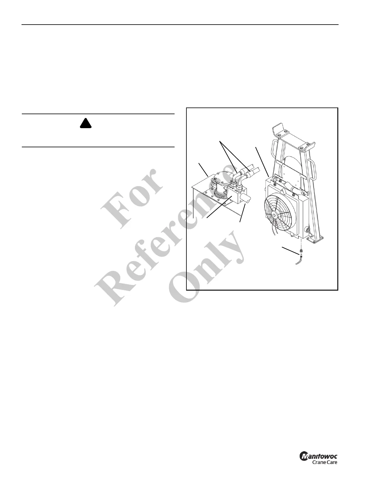
Hydraulic Oil Cooler
A hydraulic oil cooler (Figure 2-9) is located on the boom
rest. The oil cooler return circuit is in parallel with the
reservoir return circuit. A 30 psi (206 kPa) check valve in the
cooler line regulates flow through the oil cooler. When the
hydraulic oil is cold, most of the return oil goes directly to the
tank. As the oil warms up and becomes thinner, more oil
goes through the cooler.
NOTE: A temperature sensor located in swivel port (4B)
monitors the temperature of the hydraulic oil and
illuminates a light on the crane cab console when
the temperature reaches 96° C (205° F).
The oil cooler fan is controlled by a relay in VEC module. To
access the relay, remove the assess panel on the side of the
housing. A temperature switch located in the cooling core
energizes the fan relay when the oil temperature reaches 49
°C (120°F).
NOTE: If the temperature sensor in the cooling core fails,
the fan runs continuously even when the crane
ignition is off.
Oil Cooler Service & Maintenance
The heat exchanger must be kept clean to allow for efficient
operation of the cooler system. Frequent washing of the heat
exchanger core eliminates oil film, road dirt, and other
foreign object buildup on the heat exchanger fins which
reduces cooling efficiency.
Frequent inspection and tightening of hose clamp line
connections eliminates the possibility of end connection
failure due to back pressure from cold startup.
If cooler the system fails to provide adequate performance,
reduced air or oil flow through the heat exchanger is the
probable cause. Inspect the cooling fan for proper operation.
Any obstructions to air flow needs to be corrected (cooler too
close to other truck components, foreign matter in heat
exchanger fins, etc.). All hydraulic lines should be
periodically checked for obstructions, hose kinks or other
flow restrictions.
DANGER
Ensure that hydraulic system is shut down and the
pressure is relieved.
Hydraulic
Oil Cooler
FIGURE 2-9
Bypass
Valve
Fan Temperature
Switch
Return
To Oil
Cooler
Hydraulic
Tank
Fo
r
Reference
Only

 Loading...


