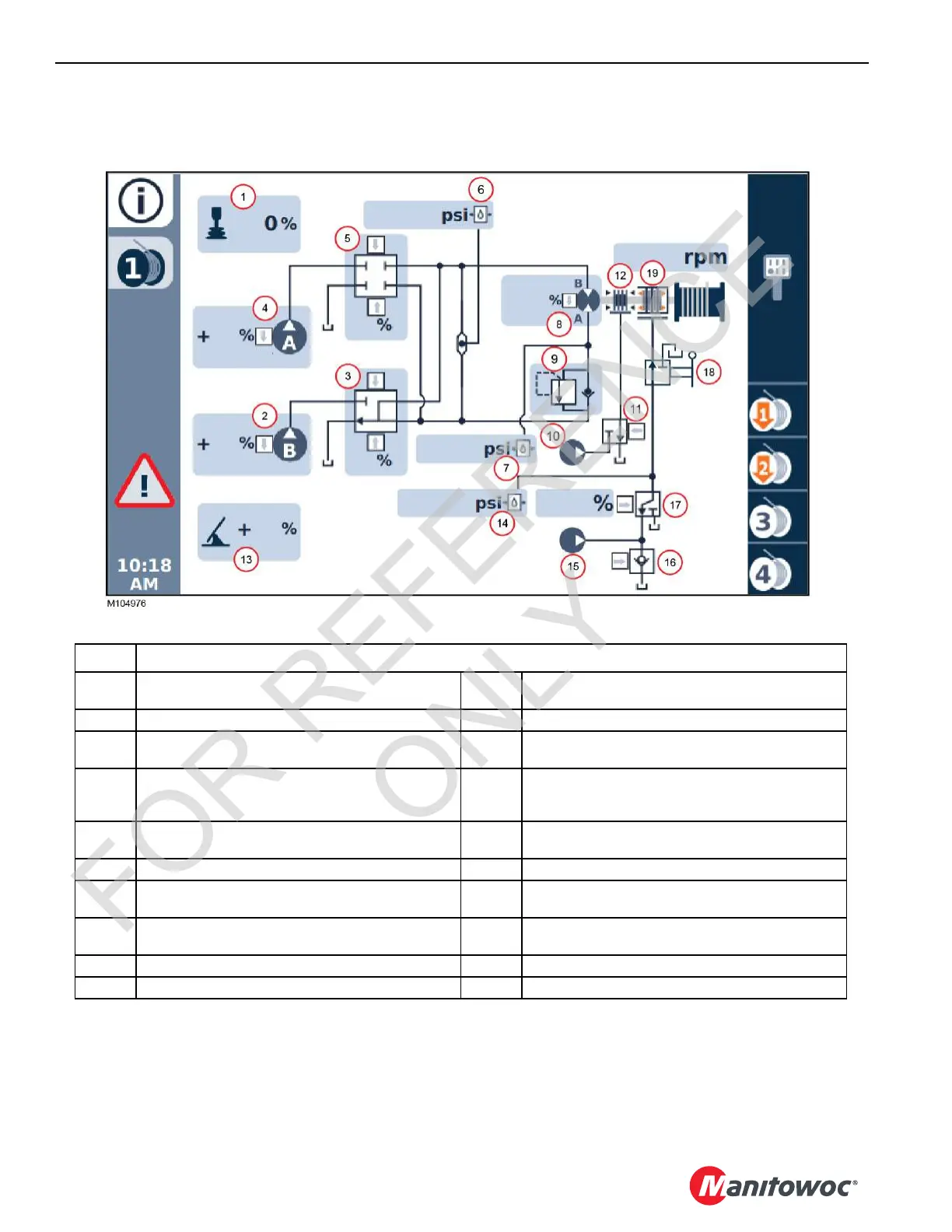
Item Drum 1 Components
1
Handle (Command -100 to 100%)
+ number = raise, – number = lower
11 Brake Valve (motor end)
2 Pump B (primary) Command (0 to 100%) 12 Brake (motor end)
3
Pump B Control Valve (Command -100 to 100%)
+ number = raise, – number = lower
13
Free Fall Brake Pedal (Command 0-100%)
0% = pedal down, 100% = pedal up
4 Pump A (secondary) (Command 0 to 100%) 14
Free Fall Brake Pressure Sensor
0 bar/psi = pedal down (applied), 70 bar (1000 psi) pedal
up (fully released)
5
Pump A Control Valve (Command -100 to 100%)
+ number = raise, – number = lower
15 Free Fall Pump
6 System Pressure Sensor 16 Free Fall System Enable Valve
7 Motor Pressure Sensor 17
Free Fall Brake Valve (Command 0-100%)
0% = pedal down, 100% = pedal up
8
Motor (command 0% = max displacement, 100% = min
displacement)
18 Free Fall Selector Valve (On-Off)
9 Load Holding Valve 19 Free Valve Brake
10 Accessory Pump
FIGURE 5-10
 Loading...


