Manitowoc Published 10-09-2020, Control # 259-06 5-25
MLC80A-1/MLC90A-1/MLC100A-1/MLC100-1 SERVICE/MAINTENANCE MANUAL HOISTS
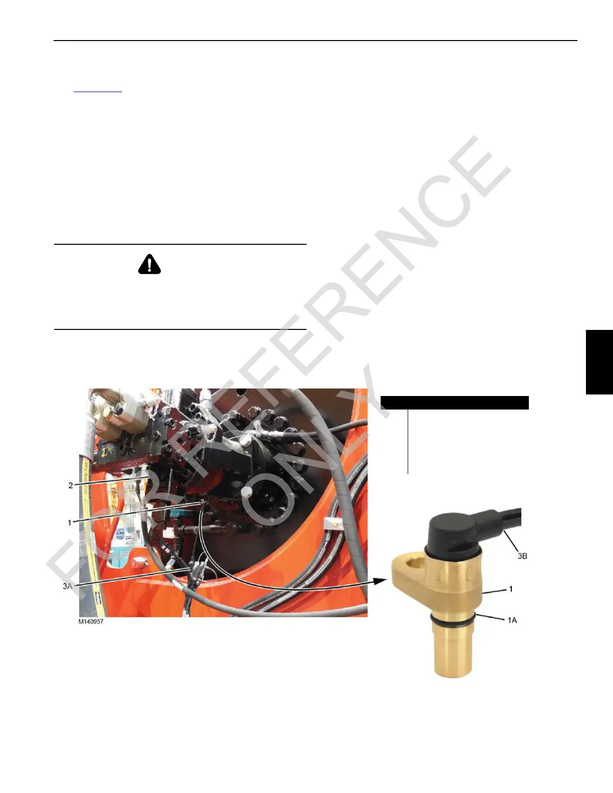
SPEED SENSOR—HOIST MOTORS
See Figure 5-18 for the following procedure.
A speed sensor (1) is installed in the drum motor (2) for each
drum. The sensor sends rotational speed and direction
information to the corresponding control module to be used
by the crane control functions.
There is no adjustment for the speed sensors.
Replacement
Replacement is required if a speed sensor is suspected of
sending faulty information to the corresponding control
module.
1. Lockout-tagout the crane.
2. Disconnect the electrical cable (3A) from the electric
cable (3B).
3. Thoroughly clean the area around the speed sensor to
prevent dirt from entering the hydraulic system.
4. Place an appropriate container under the motor to catch
any oil leakage.
5. Work quickly to prevent excess oil leakage.
6. Make sure the O-ring (1A) is installed on the new speed
sensor (1).
7. Remove the speed sensor mounting screw and the
faulty speed sensor.
8. Clean the mating surfaces and install the new speed
sensor and O-ring.
9. Install the mounting screw and tighten it to 8 ±2 Nm (6 ±
1.5 ft-lb).
10. Connect the electrical cables (3A and 3B).
11. Operate the drum and check for a steady drum speed
(rpm) and direction signal in the corresponding drum’s
Control Information Screen in the main display.
12. Make sure there is no oil leakage.
WARNING
Burn Hazard!
Hydraulic fluid will drain from the port when the speed
sensor is removed. Wait for the hydraulic fluid to cool
before removing the speed sensor.
Item Description
1 Speed Sensor
1A O-Ring
2 Drum Motor
3A Electrical Cable from Crane
3B Electrical Cable from Sensor
Typical View (all drums)
FIGURE 5-18
 Loading...


