Manitowoc Published 10-09-2020, Control # 259-06 8-3
MLC80A-1/MLC90A-1/MLC100A-1/MLC100-1 SERVICE/MAINTENANCE MANUAL UNDERCARRIAGE
• Simultaneously, the travel brakes are released to allow
travel.
The following sensors provide feedback to the control
system:
• Pump A and Pump B pressure sensors
• Left travel pressure sensor
• Right travel pressure sensor
The control system uses this feedback to adjust the pump
and motor flows to maintain the speeds commanded by the
handles.
No Travel
When the travel control handles are in the neutral position,
the travel pumps are de-stroked and the left and right travel
proportional control valves remain in the center position,
blocking hydraulic flow from the pumps to the travel motors.
The travel brake solenoid is deenergized, allowing spring
force to apply the travel brakes.
Travel Motor Flushing
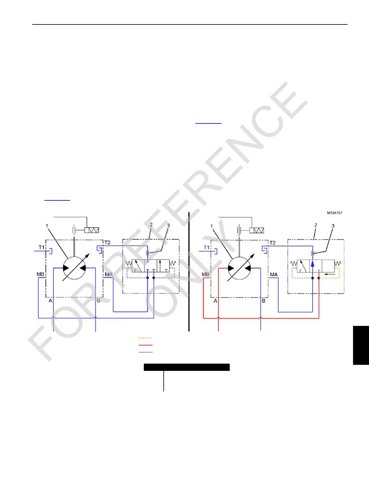
See Figure 8-1.
The purpose of the travel motor flushing circuit is to provide a
continuous flow of flushing oil to the case of both travel
motors while the crane is traveling.
Each travel motor (1) has a 3-position, pilot-operated
flushing valve (2) for controlling the flushing circuit.
When the travel system is in neutral (View A), the flushing
valve is spring centered to the closed position, and there is
no flushing oil flow through the travel motor.
When a crawler is operated (View B), oil from the pump is
delivered to the corresponding motor port via the
proportional travel control valve. For the example in
Figure 8-1
, oil is being delivered to motor port A.
In this example, system pressure from motor port MB shifts
the flushing valve open allowing return oil from motor port
MA to flow through the orifice (3). The orifice meters return
oil to the motor case port T2 and the oil returns to tank via the
motor case port T1.
When the motor is operated in the opposite direction,
pressure from motor port MA shifts the flushing valve (2) in
the opposite direction shown, and oil from motor port MB
flows through the orifice (3) and back to tank via the motor
case ports T2 and T1.
FIGURE 8-1
Pilot Pressure
System Pressure
Exhaust (tank)
Item Description
1Travel Motor
2 Flushing Valve
3 Orifice: 8 L/min (2.1 gpm)
 Loading...


