EasyManuals Logo
Home>Manitowoc>Construction Equipment>MLC100-1

Manitowoc MLC100-1 Service And Maintenance Manual

Manitowoc MLC100-1
188 pages
To Next Page IconTo Next Page
To Previous Page IconTo Previous Page
Page #96 background imageLoading...
Page #96 background image
HOISTS MLC80A-1/MLC90A-1/MLC100A-1/MLC100-1 SERVICE/MAINTENANCE MANUAL
5-10
Published 10-09-2020, Control # 259-06
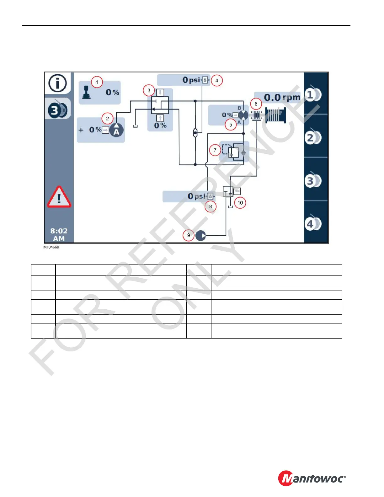
Drum 3 Hydraulic Schematic
A detailed hydraulic schematic is provided at the end of Section 2 in this Service Manual.
FIGURE 5-6
Item Drum 3 Components 6 Brake
1
Handle (Command -100 to 100%)
+ number = raise, – number = lower
7 Load Holding Valve
2 Pump A (Command 0 to 100%) 8 Motor Pressure Sensor
3
Pump A Control Valve (Command -100 to 100%)
+ number = raise, – number = lower
9 Accessory Pump
4 System Pressure Sensor 10 Brake Valve
5
Motor (Command 0=max displacement, 100%= min
displacement)
FOR REFERENCE
ONLY

Table of Contents

Other manuals for Manitowoc MLC100-1

Questions and Answers:

Question and Answer IconNeed help?

Do you have a question about the Manitowoc MLC100-1 and is the answer not in the manual?

Manitowoc MLC100-1 Specifications

General IconGeneral
BrandManitowoc
ModelMLC100-1
CategoryConstruction Equipment
LanguageEnglish

Related product manuals