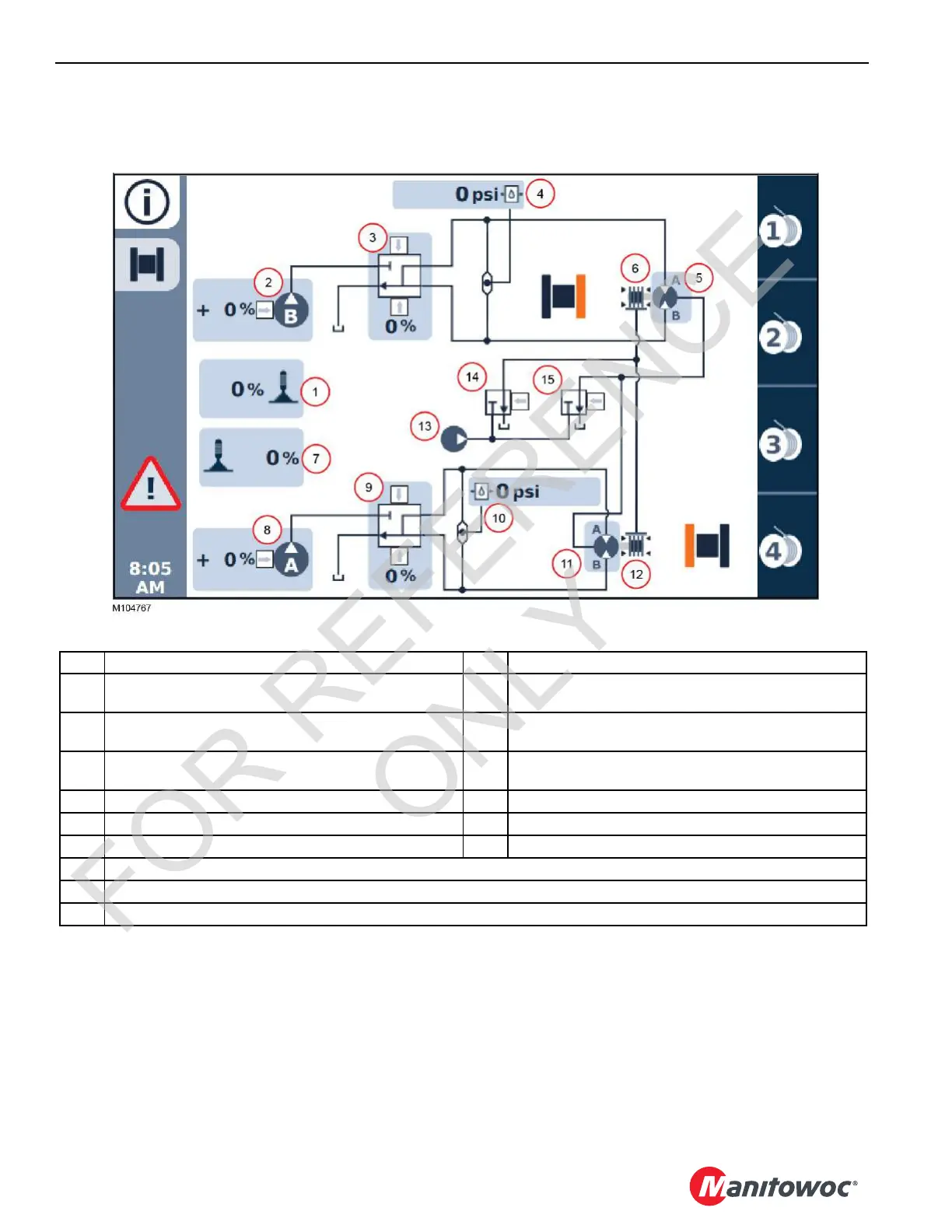
EasyManuals Logo
Home>Manitowoc>Construction Equipment>MLC100-1

Manitowoc MLC100-1 Service And Maintenance Manual

Manitowoc MLC100-1
188 pages
To Next Page IconTo Next Page
To Previous Page IconTo Previous Page
Page #162 background imageLoading...
Page #162 background image
UNDERCARRIAGE MLC80A-1/MLC90A-1/MLC100A-1/MLC100-1 SERVICE/MAINTENANCE MANUAL
8-4
Published 10-09-2020, Control # 259-06
Travel Hydraulic Diagram
A detailed hydraulic schematic is provided at the end of Section 2 in this Service Manual.
FIGURE 8-2
Item RIGHT Crawler Components Item LEFT Crawler Components
1 Control Handle (Command -100 to 100%)
+ number = forward, – number = reverse
7 Control Handle (Command -100 to 100%)
+ number = forward, – number = reverse
2 Main Pump B (Command -100 to 100%)
+ number = forward, – number = reverse
8 Pump A (Command -100 to 100%)
+ number = forward, – number = reverse
3 Proportional Control Valve (Command -100 to100%)
+ number = forward, – number = reverse
9 Proportional Control Valve (Command -100 to100%)
+ number = forward, – number = reverse
4 Pressure Transducer 10 Pressure Transducer
5 Motor 11 Motor
6 Brake 12 Brake
13
Accessory Pump
14
Brake Valve (right and left)
15 2-Speed Valve (right and left)
FOR REFERENCE
ONLY

Table of Contents

Other manuals for Manitowoc MLC100-1

Questions and Answers:

Question and Answer IconNeed help?

Do you have a question about the Manitowoc MLC100-1 and is the answer not in the manual?

Manitowoc MLC100-1 Specifications

General IconGeneral
BrandManitowoc
ModelMLC100-1
CategoryConstruction Equipment
LanguageEnglish

Related product manuals