UNDERCARRIAGE MLC80A-1/MLC90A-1/MLC100A-1/MLC100-1 SERVICE/MAINTENANCE MANUAL
8-10
Published 10-09-2020, Control # 259-06
TURNTABLE BEARING ALIGNMENT
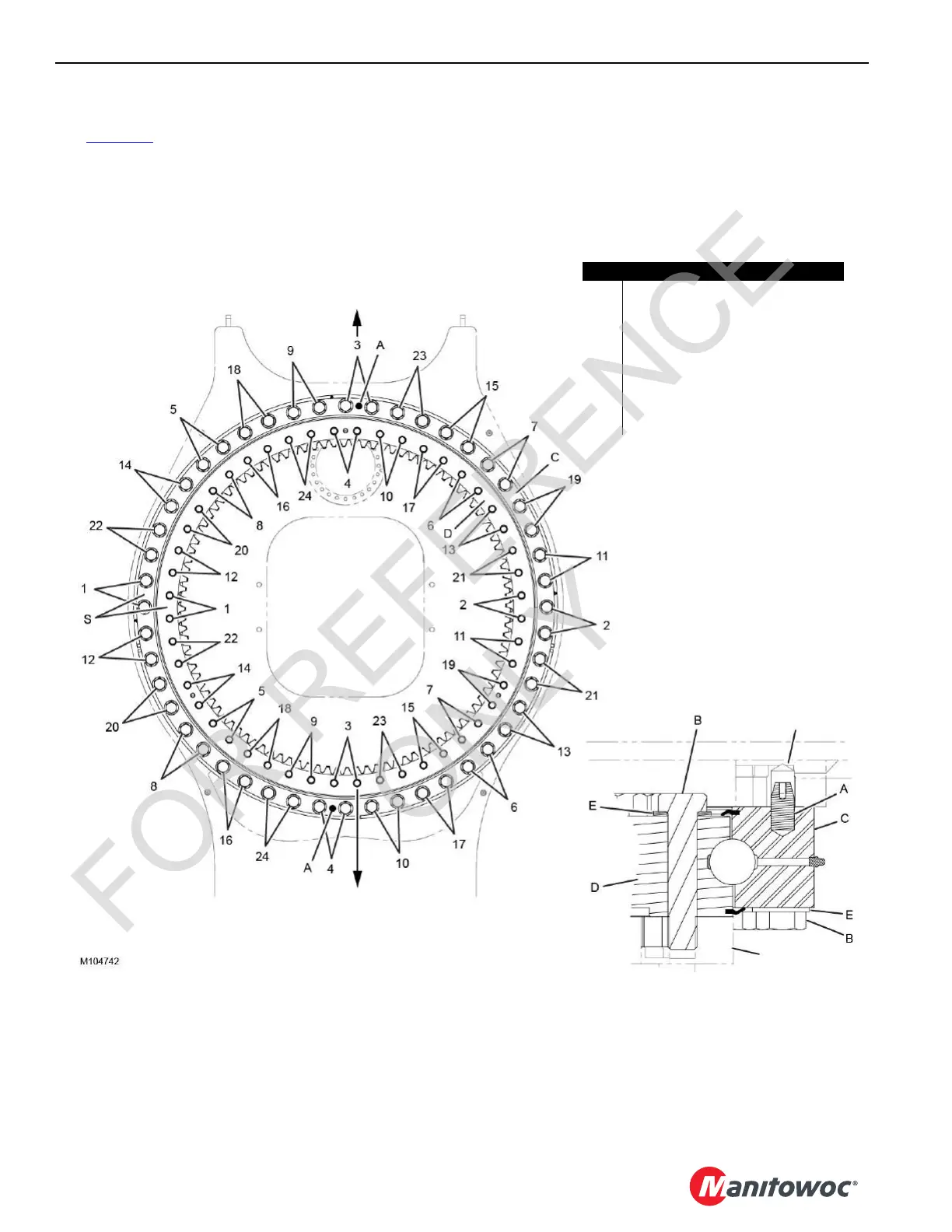
See Figure 8-7 for the following.
Install the inner ring (D) so the S stamp is towards the side of
the carbody.
Two shear pins (A) are installed in the rotating bed to locate
the outer ring (C) with the rotating bed.
Verify the S stamp in the outer ring (C) is toward the side of
the rotating bed.
FIGURE 8-7
Item Description
A Shear Pin (2 places)
B 1-1/4 in—7 x 6 in Long Heavy Head
Special Grade Bolt with Special Flat
Washer
• 48 Places Outer Ring
• 48 Places Inner Ring
C Outer Ring
D Inner Ring
E Washer Shim
FRONT
of Rotating Bed
FRONT
of Carbody
Rotating Bed
Carbody
 Loading...


