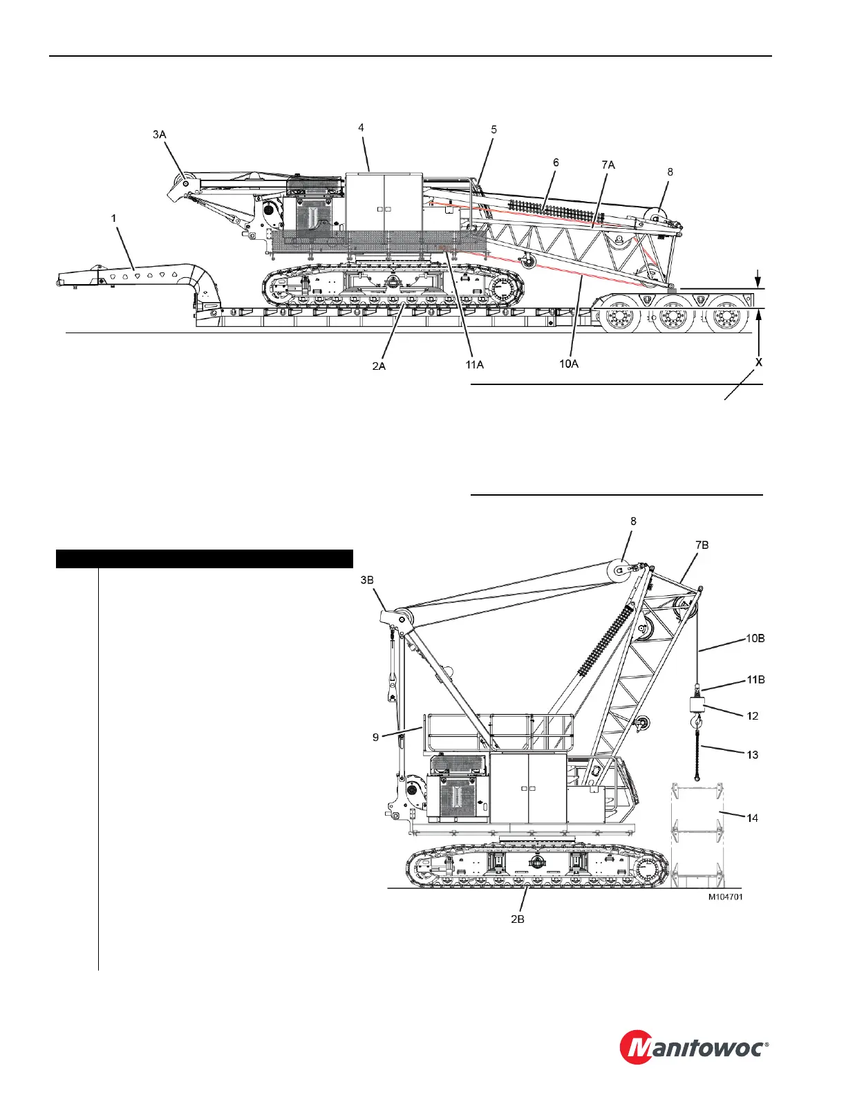
Item Description
1 Double Drop Deck, 3-Axle Trailer (minimum)
with Removable Goose Neck
2A Crawlers Retracted (without carbody
counterweight)
2B Crawlers Extended
3A Gantry Lowered
3B Gantry Raised
4 Upperworks (without crane counterweight)
5 Operator Cab
6 Boom Stops
7A Boom Butt Lowered
7B Boom Butt Raised
8 Equalizer
9 Handrails Raised
10A Load Line from Front Drum (stored for shipping)
10B Load Line from Front Drum (working)
11A Button Socket (stored for shipping)
11B Button Socket (working)
12 Hook-and-Weight Ball
13 3-Leg Chain Sling
14 Crane Counterweight (assembled on ground)
X 457 mm (18 in) Minimum for Gantry Raising or
Damage can Occur
Figure 4-3
Shipping Configuration
• Max shipping width = 3.7 m (12 ft)
• Max shipping height = 4.1 m (13 ft 6 in)
• Shipping weight with Drum 3 and Wire Rope = 42 563 kg (93,835 lb)
• Shipping weight without Drum 3 = 41 300 (91,050 lb)
Self-Erect Configuration
CAUTION
Avoid Wire Rope Damage!
To avoid wire rope damage, the boom butt must be
blocked at dimension X prior to raising the gantry.
Dimension X is measured from trailer deck to
underside of bottom boom butt connectors.