Manitowoc Published 12-10-19, Control # 258-05 4-37
MLC90A-1/MLC100-1 OPERATOR MANUAL SETUP AND INSTALLATION
Legend for Figure 4-22.
Connect Boom Butt to Boom Top Electric
Cables
See Figure 4-22.
1. STOP the engine.
2. Prior to connecting the electric cables, remove the dust
caps or shorting plugs, and thoroughly clean the cable
connectors.
3. Apply dielectric grease to the cable connectors.
4. Unlock the cable reel (2, View C) and pay out the
required length of boom extension cable (1).
5. Route the boom extension cable (1) up the boom,
remove the dust cap (1A), and connect the boom
extension cable to the boom top connector (3, View A).
6. Connect the strain relief on the boom extension cable (1)
to the carabiner in the boom top (see View C,
Figure 4-24 on page 4-38
).
7. Connect the other end of the boom extension cable (1,
View C) to the boom connector (4) and lock the cable
reel in position with the locking lever (2A).
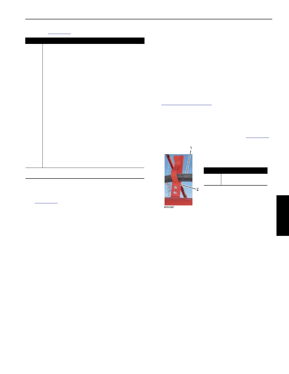
8. Secure the boom extension cable to the storage
brackets in the boom sections as shown in Figure 4-23
.
Item Description
1 Boom Extension Cable (WBBI-P2)
1A Dust Cap
2 Cable Reel
2A * Handle
2B * Locking Lever
3 Boom Top Connector (WBT1-J1)
3A Dust Cap
4 Boom Connector (WRL1-J9)
5 Camera Extension Cable (WBB2 CCTV)
5A Dust Cap
6 Storage Bracket
7 Attachment Connector (WBT1-J2)
7A Shorting Plug
8 Lower Point Block-Up Limit Cable (WBT1-P4)
8A Dust Cap
9 Second Lower Point Block-Up Limit Cable (WBT1-P3)
A Shorting Plug
10 Anemometer Cable (WBT1-P6)
10A Dust Cap
11 Position Light Cable (WBT1-P5)
11A Dust Cap
* Handle (2A) and locking lever (2B) may be on inboard side of
cable reel.
Item Description
1 Electric Cable
2 Cable Storage Bracket
Figure 4-23
 Loading...


