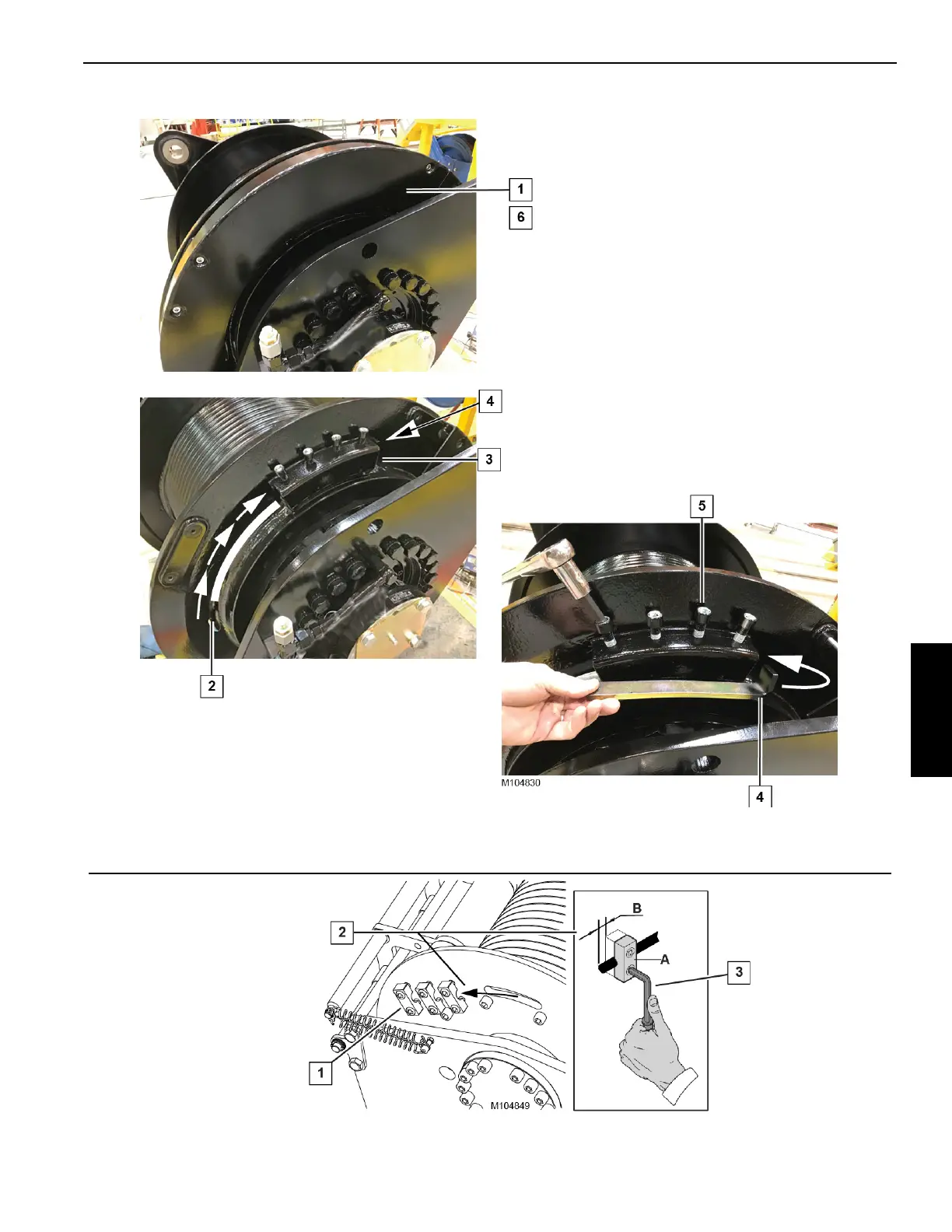
Figure 4-54
Remove half of the guard from the drum.
Route the wire rope from the inside of the
drum, through the hole in the drum flange,
and into the rope socket on the outside of the
drum flange.
Position the end of the rope at or slightly
beyond the end of the rope socket.
Install the clamp bar above the wire rope. Make sure
there is no rope seizing under the clamp bar.
Tighten the clamp screws
(see Torque Note).
Reinstall the guard.
Torque Note
• Torque clamp screws to 206 Nm (150 ft-lb)
• Do not use Loctite
• Tuflok® thread-locking compound has been applied
to the screws. The screws can be removed/installed
several times before reapplying the compound.
Drums 1, 2, and 4
Figure 4-55
Drum3
Securely tighten the
clamp screws to 207
Nm (150 ft-lb).
Loosen the clamp screws.
Route the wire rope from the inside of
the drum, through the hole in the
drum flange, and under the clamps
“A” on the outside of the drum flange.
The rope protrusion “B” must be at
least twice the wire rope’s diameter.
 Loading...


