
Do you have a question about the Manitowoc QF0400 and is the answer not in the manual?
| Model | QF0400 |
|---|---|
| Width | 30 inches |
| Voltage | 115V |
| Condenser | Air-cooled |
| Water Connection | 3/8" FPT |
| Refrigerant | R-404A |
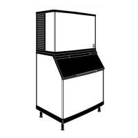
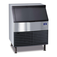
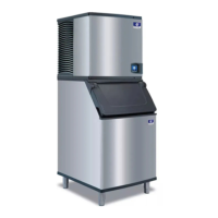
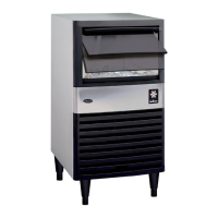
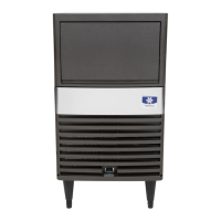
| Type | Undercounter |
| Ice Production | 400 lbs per day |
| Ice Type | Cube |
| Weight | 180 lbs |
| Power Supply | 115V, 60Hz |
| Water Usage | 4.5 gallons per 100 lbs of ice |
Alerts to potential personal injury situations.
Alerts to situations that could damage equipment.
Information listing various model numbers.
Guide to understanding model number components.
Owner warranty registration and coverage details.
Criteria for selecting installation location.
Recommended clearances for operation and servicing.
Requirements for fuses and circuit breakers.
Tables detailing circuit ampacity requirements.
Guidelines for drain line installation.
Line set specs for traditional remote units.
Diagram identifying QF400 air-cooled components.
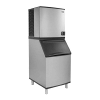
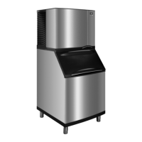
Component diagrams for QF800/QC700 models.
Steps for cleaning heavily scaled ice machines.
Routine cleaning and sanitizing procedure.
Preventative maintenance steps for QF0400.
Preventative maintenance for specific SN/SF models.
Heavily scaled cleaning procedure for QC/QF models.
Disassembly steps for QF400 for cleaning.
Steps for cleaning air-cooled condensers.
Winterization procedures for remote ice machines.
Sequence of operation for ice making in QF/QC models.
Safety features built into the control board.
Explanation of the SafeGuard system.
Troubleshooting the 'No Water' SafeGuard condition.
Steps to diagnose why the ice machine is not running.
Checklist to resolve water system problems.
Measure and calculate 24-hour ice production.
Checklist for high discharge pressure.
Checklist for low suction pressure.
Procedure to check the main fuse.
Procedure to check the water float valve.
Check procedure for the LPCO control.
Analysis of equalization valve failure modes.
Steps to adjust the thermostat's setpoint value.
Explanation of fault codes on LCD.
Function and sensing of Hall Effect Switch #1.
Function of Hall Effect Switch #2.
Procedure to check compressor winding resistance.
Steps to diagnose faulty compressor capacitors.
Function and troubleshooting of starting capacitors.
Function and check procedure for fan cycle control.
Operation of headmaster control valve during freeze cycle.
Refrigerant recovery for self-contained units.
Refrigerant recovery for remote air-cooled models.
Cleanup procedures based on contamination symptoms.
Steps for removing gear box assembly from QF0400.
Guide to identify correct re-build kit.
Steps for removing the evaporator from QF0400.
Specifications for HPCO control.
Operating characteristics for SN012A/SN020A models.
Operating data for QF0400A stainless steel models.
Operating data for SF0400A models.
Operating data for SF0400W models.
Electrical diagrams illustrating machine wiring.
Diagrams showing refrigerant tubing layout.
Wiring diagram for QF0400 models.
Wiring diagram for QC0700/QF0800 models.
Wiring diagram for QF2200 models.