AXLES/DRIVE SHAFTS/WHEELS AND TIRES CD5515-2/YB5515-2 SERVICE MANUAL
8-14 Published 1-20-2017, Control# 483-02
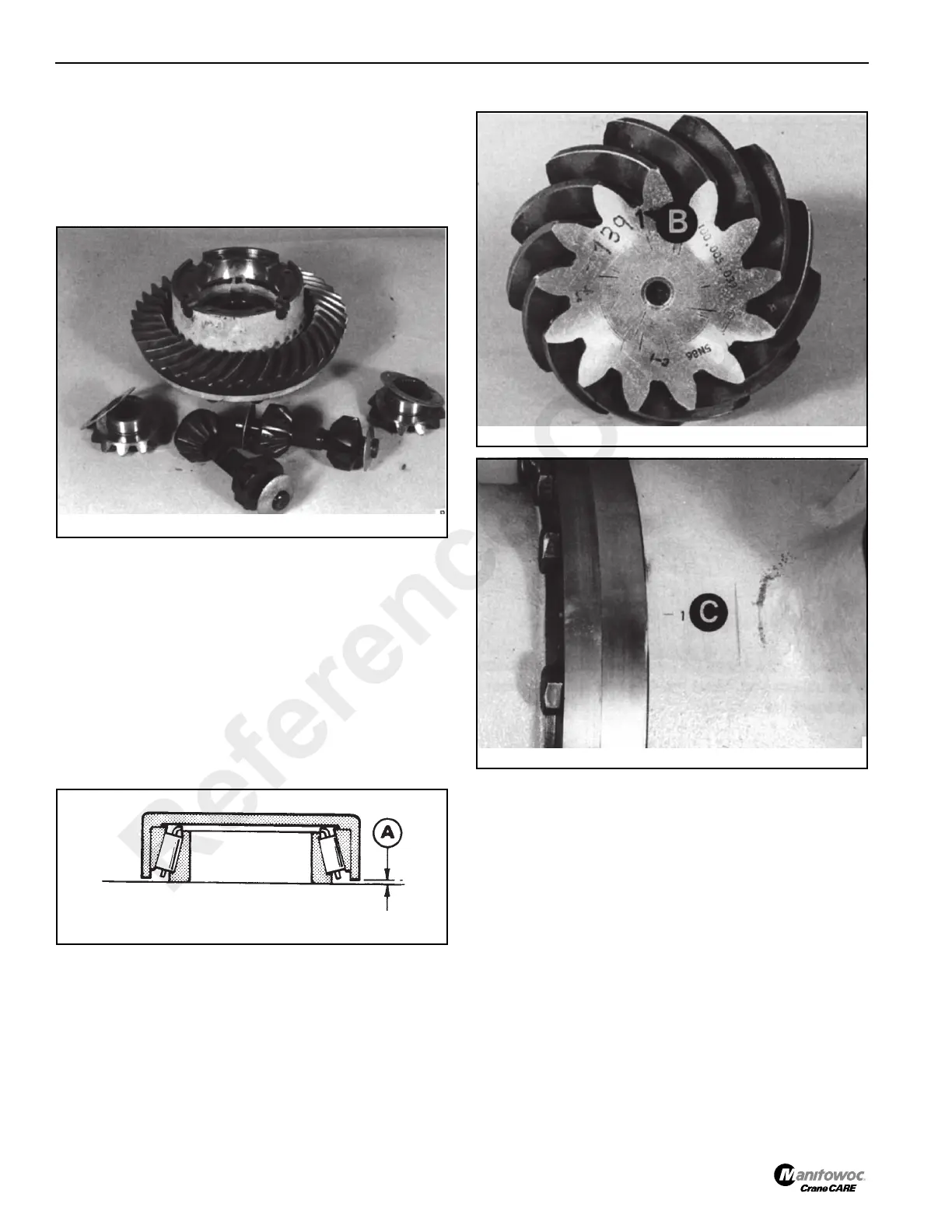
c. Remove the differential gears and spherical
washers Figure 8-24. Pull off both differential
bearing cones.
If required, remove the crownwheel to differential
case half retaining bolts and remove the
crownwheel.
Assembly
Pinion Depth Setting Procedure
Determine the pinion depth setting as follows:
NOTE: See page 8-15 for general guidance on
crownwheel and pinion adjustment.
1. Assemble the pinion inner bearing and its cup on a flat
surface.
2. Place the pinion bearing measuring cup over the bearing
assembly Figure 8-25. Measure gap A. Add tool depth of
30.1 mm. (1.18 in) to gap A to give bearing depth.
3. Find the mounting distance value B Figure 8-26 on the
pinion and deviation C Figure 8-27 on the drive head
housing. Both units are in millimeters. To convert
millimeters to inches, multiply millimeters by 0.03937.
4. If dimension B is positive, add it to the bearing depth. If
dimension B is negative, subtract it from the bearing
depth. See example Crownwheel and Pinion Adjustment
on page 8-15.
5. If dimension C is positive, subtract it from the total. If
dimension C is negative, add it to the total. See example
Crownwheel and Pinion Adjustment on page 8-15.
6. Subtract the result from the standard value of 31.19 mm
(1.23 inches) to give the required shim thickness. See
example Crownwheel and Pinion Adjustment on
page 8-15.
Reference Only
 Loading...


