EasyManua.ls Logo

Matrix C7XE-05 User Manual

Matrix C7XE-05
55 pages
To Next Page IconTo Next Page
To Previous Page IconTo Previous Page
Page #24 background image
43
42
CHAPTER 8: TROUBLESHOOTING
8.11 TROUBLESHOOTING - ERROR 03A5 / 03A6
ERROR CODE 03A5 / 03A6
1) SYMPTOM:
03A5 - After program start, GUI can't load program.
03A6 - After GUI load program, the program can't be started.
2) SOLUTION:
1) Using USB disk to update the latest GUI.
2) If the error still happened after update, replacement LMM board.
8.10 ERROR CODE TROUBLESHOOTING - 02C3
CHAPTER 8: TROUBLESHOOTING
ERROR CODE 02C3 (Frame IR sensors error)
1) SYMPTOM:
a. The frame IR sensors are no communication or disconnected over 3 seconds.
b. Once power on, the frame IR sensors are no power or hidden over 3 seconds.
c. After power on, the frame IR sensors are no power or hidden over 4 hours.
2) SOLUTION:
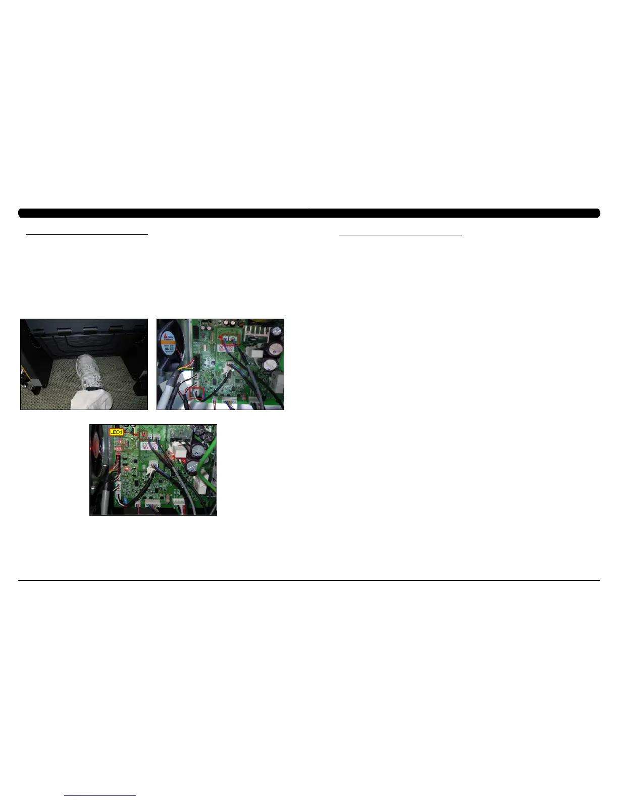
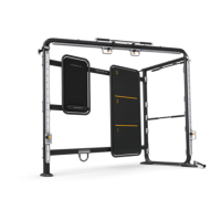
a. Check if there's something in the control zone 3 IR sensors. (Figure A).
b. Check the connection of the frame IR cable from the LCB to the frame IR sensors (Figure B).
c. Check if LED1 on the small transfer board is flashing (Figure C).
- If not, replace the small transfer board.
- If yes, replace the frame IR cables (transmission & receiver).
FIGURE A FIGURE B
FIGURE C

Table of Contents

Question and Answer IconNeed help?

Do you have a question about the Matrix C7XE-05 and is the answer not in the manual?

Matrix C7XE-05 Specifications

General IconGeneral
BrandMatrix
ModelC7XE-05
CategoryFitness Equipment
LanguageEnglish

Summary

CHAPTER 1: SERIAL NUMBER LOCATION

1.1 SERIAL NUMBER LOCATION

Details the location for finding the serial number on the unit.

CHAPTER 2: IMPORTANT SAFETY INSTRUCTIONS

2.1 READ AND SAVE THESE INSTRUCTIONS

Provides essential safety guidelines and precautions for operating the equipment.

2.2 ELECTRICAL REQUIREMENTS

Specifies electrical requirements, circuit needs, and grounding for safe operation.

CHAPTER 5: MANAGER MODE

5.1 MANAGER MODE OVERVIEW

Explains how to access and use Manager Mode for customizing club settings.

CHAPTER 8: TROUBLESHOOTING

8.1 ELECTRICAL DIAGRAMS

Provides detailed wiring schematics for various components of the unit.

8.1 ELECTRICAL DIAGRAMS - CONTINUED

Continues detailed wiring schematics, illustrating connections between boards.

8.3 ERROR CODE TROUBLESHOOTING - 01AC

Troubleshoots error code 01AC related to ECB over current.

8.4 ERROR CODE TROUBLESHOOTING - 01AF

Troubleshoots error code 01AF indicating a disconnected electro-magnet (ECB).

8.5 ERROR CODE TROUBLESHOOTING - 02A0

Troubleshoots error code 02A0 related to encoder or speed sensor issues.

8.6 ERROR CODE TROUBLESHOOTING-02BE/02BF

Troubleshoots DC brake errors (02BE/02BF) for movement in stop mode.

8.7 ERROR CODE TROUBLESHOOTING - 02CO

Troubleshoots DC brake errors (02C0) occurring in manual mode.

8.8 ERROR CODE TROUBLESHOOTING - 02C1

Troubleshoots speed tracking errors (02C1) indicating RPM deviation.

8.9 ERROR CODE TROUBLESHOOTING - 02C2

Troubleshoots Control Zone 3 IR sensor communication errors (02C2).

8.10 ERROR CODE TROUBLESHOOTING - 02C3

Troubleshoots frame IR sensor communication errors (02C3).

8.11 TROUBLESHOOTING - ERROR 03A5/03A6

Addresses GUI loading and program start errors (03A5/03A6).

8.12 TROUBLESHOOTING - ERROR 03A7

Troubleshoots issues loading video in the Virtual Active program (03A7).

8.13 TROUBLESHOOTING - ERROR 03A8

Troubleshoots machine type setting mismatch with LCB or MCB (03A8).

8.14 ERROR CODE TROUBLESHOOTING - 04A0

Troubleshoots UCB communication errors (04A0) or disconnection.

8.15 ERROR CODE TROUBLESHOOTING - 04B0

Troubleshoots LCB communication response issues (04B0).

8.16 TROUBLESHOOTING - NO POWER TO THE CONSOLE

Diagnoses and resolves issues related to the console not receiving power.

8.17 TROUBLESHOOTING - HEART RATE ISSUES

Addresses problems with no heart rate reading or erratic heart rate display.

8.17 TROUBLESHOOTING - HEART RATE ISSUES - CONTINUED

Continues troubleshooting heart rate issues, focusing on wiring and grip continuity.

8.18 TROUBLESHOOTING - TOGGLE ISSUES

Diagnoses and resolves problems with the grip toggle response and console feedback.

8.18 TROUBLESHOOTING - TOGGLE ISSUES - CONTINUED

Further troubleshooting for toggle issues, checking wiring continuity and console function.

CHAPTER 9: PART REPLACEMENT GUIDE

9.21 TESTING THE CLIMB MILL

Comprehensive testing procedure after installation or part replacement.

CHAPTER 11: SOFTWARE UPGRADE PROCEDURE

11.1 SOFTWARE UPGRADE PROCEDURE FOR UCB

Finalizes UCB software upgrade, including service mode checks and value recording.

11.2 SOFTWARE UPGRADE PROCEDURE FOR LCB

Procedure for upgrading the Lower Control Board (LCB) software via USB.

Related product manuals