75
74
9.10 DRIVE SET REPLACEMENT - CONTINUED
CHAPTER 9: PART REPLACEMENT GUIDE
9) While a tech is pushing the drive set towards the front of the unit (the drive set will still be supported by the guide screw - Figure G), the other
tech should remove the chain from the sprocket simultaneously (Figure H).
10) Remove the drive set from the unit (Figure I). note: The drive axle will need to be rotated so that the pulleys are horizontal to t through
the side covers (Figure J).
11) Reverse Steps 1-10 to install a new drive set. note: Make sure that the wiring disconnected in Step 5 gets connected correctly. Refer to
Figures K & L. note: Torque the bolts removed in Step 7 to 40N-m.
12) Test the Climb Mill for function as outlined in Section 9.21.
FIGURE HFIGURE G
FIGURE I
FIGURE LFIGURE K
FIGURE J
9.11 CHAIN REPLACEMENT
CHAPTER 9: PART REPLACEMENT GUIDE
1) Turn off the power and disconnect the cord from the machine.
2) Remove the side covers as outlined in Section 9.1.
3) Remove at least 3 sets of stairs as outlined in Section 9.9 to expose a signicant portion of the chain.
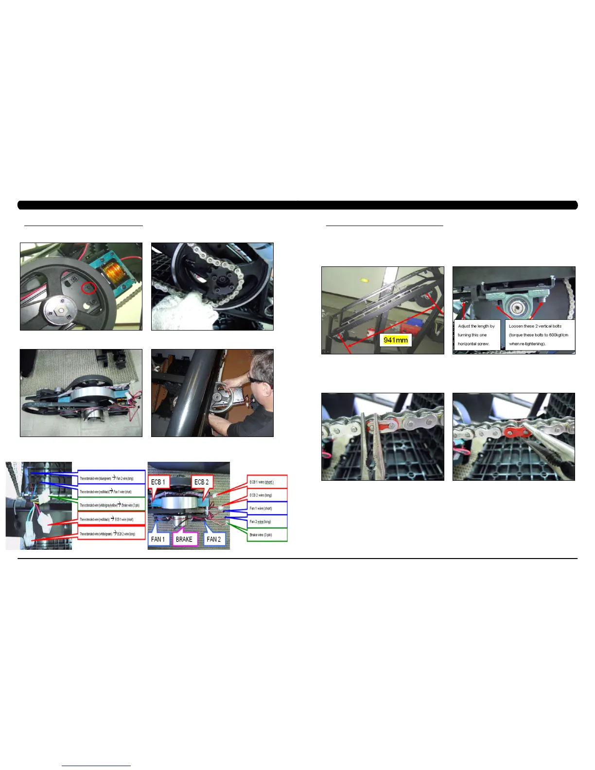
4) Before removing the chain, measure the distance of the chain run from the middle of the front bearing seat to the middle of the rear bearing
seat (Figure A). This distance should be 941mm.
5) If this length is not 941mm, it needs to be adjusted. Loosen the vertical bolts on the bearing seat, then adjust the length by adjusting the
horizontal screw. Tighten the vertical bolts to tighten the bearing seat in place. The vertical bolts should be torqued to 60 N-m.
6) Rotate the chain until a spring clip is in a convenient location and remove it (Figure C). note: This chain link will normally be painted to
make it easier to identify.
7) Remove the join plate on the chain (Figure D).
FIGURE BFIGURE A
FIGURE C
FIGURE D
 Loading...