51
50
CHAPTER 8: TROUBLESHOOTING
8.17 TROUBLESHOOTING - HEART RATE ISSUES - CONTINUED
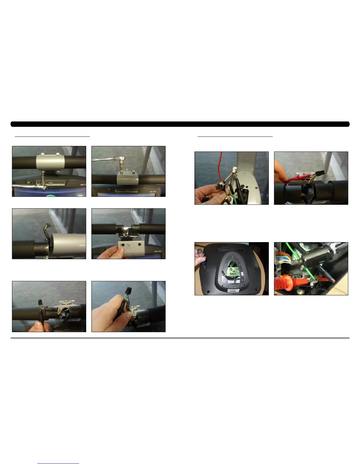
- Remove the 2 screws going into the handlebar connection frame from the bottom (Figure E).
- Remove the 3 screws going into the handlebar connection frame from the top (Figure F).
- Pull the handlebars out of the handlebar connection frame, and disconnect the HR wiring on each side (Figure G).
- Remove the handlebar connection frame from the unit (Figure H).
- Perform a continuity test on the wiring going from the HR grip to the handlebar connection frame. With a multi-meter set for ohms,
place one prong on the HR grip wiring coming out of the handlebar (Figure I) and one prong on the HR plate. The HR wiring is red, black, and
white (match red with red and white with white). For example, the red wire on the left HR grip wiring should correspond with the left top plate.
An ohm reading of less than 1 should be expected. If this reading is higher than 1, or if there is not a reading, replace this section of the HR
grip wiring.
- Repeat the previous step with the opposite side HR grip wiring (Figure J).
FIGURE FFIGURE E
FIGURE JFIGURE I
FIGURE HFIGURE G
8.17 TROUBLESHOOTING - HEART RATE ISSUES - CONTINUED
CHAPTER 8: TROUBLESHOOTING
- Remove the console and perform a continuity test on the wiring going from the handlebar connection frame to the console. With a
multi-meter set for ohms, place one prong on the HR grip wiring coming out of the console mast (Figure K) and one prong on the wiring that
connects to the handlebar wiring (Figure L - match red with red and white with white). An ohm reading of less than 1 should be expected. If this
reading is higher than 1 or if there is not a reading, replace this section of HR grip wiring.
b. If your problem is not with the HR grips, a continuity check should be performed on the unit to verify that the console is properly grounded
(see Service Bulletin – Continuity Test on Matrix Climb Mills).
- Once the console grounding has been verified, the heart rate board ground wire should be verified.
- Remove the 6 screws holding the console back to the front (Figure M).
- Check to make sure that the HR board ground wire is plugged into the console ground wire that plugs into the ground wire run down the
console mast. Retest for HR if not properly connected.
- Remove the 2 screws holding the HR board to the console frame.
- With your multi-meter set for ohms, place one prong of your multi meter on the ground wire coming from the HR board (Figure N) and
the other on the console ground wire that comes out of the console and plugs into the ground wire going down the console mast. An ohm
reading of less than 1 should be expected. If this is higher than 1 or if there is not a reading, replace the HR board ground wire.
- If no problems were found using the troubleshooting above, replace the HR board.
- If the HR board does not solve the issue, replace the console.
FIGURE LFIGURE K
FIGURE NFIGURE M
 Loading...