CHARGING & STARTING SYSTEM
90-883728 JULY 2001 Page 2B-17
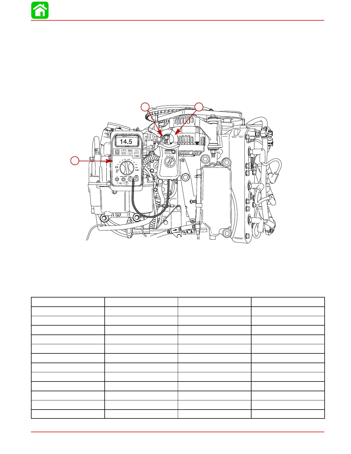
Current Output
NOTE: Before conducting current output test, assure that all boat electrical accessories
are turned OFF.
1. With engine shut off, install ammeter with clamp-on current probe (capable of reading
60+ amperes) onto alternator charging conductor (10 AWG Red Wire).
2. Start engine and allow to warm up.
3. Battery voltage should be between 14.2 and 15.0 VDC for all engine RPMs.
Alternator output current should correspond with graph below.
58882
c
b
a
a-Ammeter (DMT 2000 Digital Tachometer Multimeter 91-854009A1)
b-Clamp-On Current Probe (91-802650)
c-Alternator Charging Conductor (10 AWG Red Wire)
NOTE: Alternator amperage output can vary by as much as 10% due to heat buildup from
the numbers listed below. Alternator output listed below was with a battery loaded at 12.6
volts.
RPM AMPS @ ALTERNATOR AMPS @ BATTERY ENGINE DRAW AMPS
600 21 16 5
1000 37 31 6
1500 44 36 8
2000 48 39 9
2500 50 40 10
3000 51 41 10
3500 51 41 10
4000 52 42 10
4500 52 42 10
5000 52 42 10
5500 52 42 10
5750 52 42 10
 Loading...

