CHARGING & STARTING SYSTEM
90-883728 JULY 2001 Page 2B-21
Starter System
NOTE: Early production engines will be equipped with centrifugal bendix type starter mo-
tors. Later production engines will be equipped with solenoid driven bendix type starter
motors.
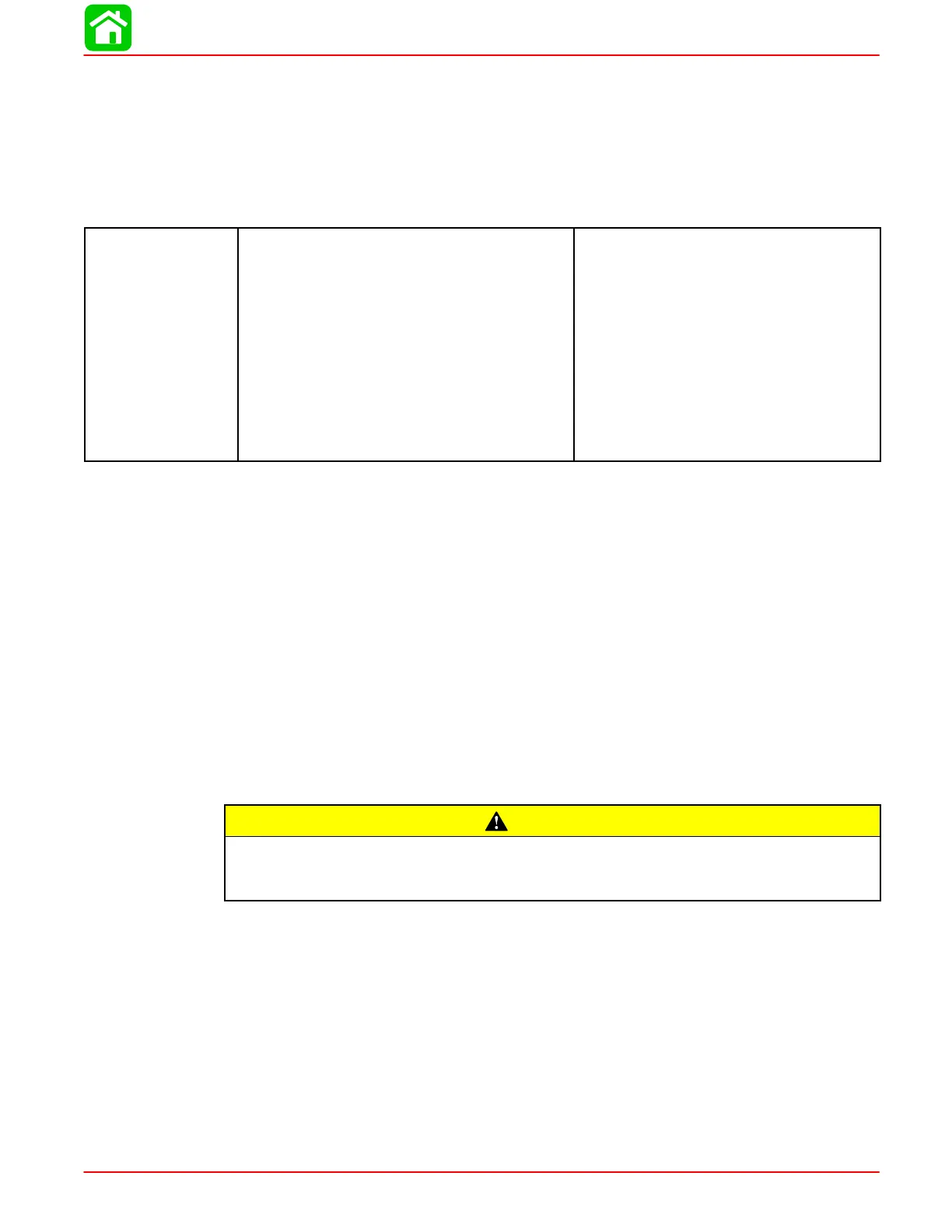
Starter Motor Amperes Draw
STARTING
SYSTEM
Electric Start – All Models
Centrifugal Bendix
Starter Draw (Under Load)
Starter Load (No Load)
Minimum Brush Length
Solenoid Driven Bendix
Starter Draw (Under Load)
Starter Load (No Load)
Minimum Brush Length
Battery Rating
165 Amperes
30 Amperes
0.25 in. (25.4 mm)
175 Amperes
60 Amperes
0.25 in. (25.4 mm)
Min. 630 Marine Cranking Amps
(MCA) or 490 Cold Cranking Amps
(CCA)
Starter System Components
Battery
Starter Solenoid
Neutral Start Switch
Starter Motor
Ignition Switch
Description
Purpose – to crank the engine. The battery supplies electricity to activate the starter mo-
tor. When the ignition switch is turned to the “START” position, the starter solenoid is ener-
gized and completes the starter circuit between the battery and starter.
The neutral start switch opens the starter circuit when the shift control lever is not in neu-
tral thus preventing accidental starting when the engine is in gear.
CAUTION
The starter motor may be damaged if operated continuously. DO NOT operate
continuously for more than 30 seconds. Allow a 2 minute cooling period between
starting attempts.
 Loading...

