OUTBOARD MOTOR INSTALLATION
90-883728 JULY 2001 Page 1D-9
Shift Cable
Install cables into the remote control following the instructions provided with the remote
control.
NOTE: Install the shift cable to the engine first. The shift cable is the first cable to move
when the remote control handle is moved out of neutral.
COUNTER ROTATION OUTBOARDS
Counter rotating (left hand) gear cases can be identified by a “L” stamped into the end of
the propeller shaft.
The Quicksilver Dual Engine Console Mount Control, P/N 88688A22 or 88688A52, is re-
quired to shift the counter rotation outboard. The installation instructions shipped with the
control explain the procedure required to connect this control to a counter rotation out-
board.
IMPORTANT: If the counter rotation outboard is rigged similar to a standard rota-
tion outboard OR if a standard rotation outboard is rigged similar to a counter rota-
tion outboard, the reverse gear and bearing in the gear case must function as for-
ward gear. THE REVERSE GEAR/BEARING ARE NOT DESIGNED TO CARRY THE
SUSTAINED LOADS THAT ARE GENERATED WHEN RUNNING UNDER CONSTANT
HIGH RPM AND THRUST CONDITIONS.
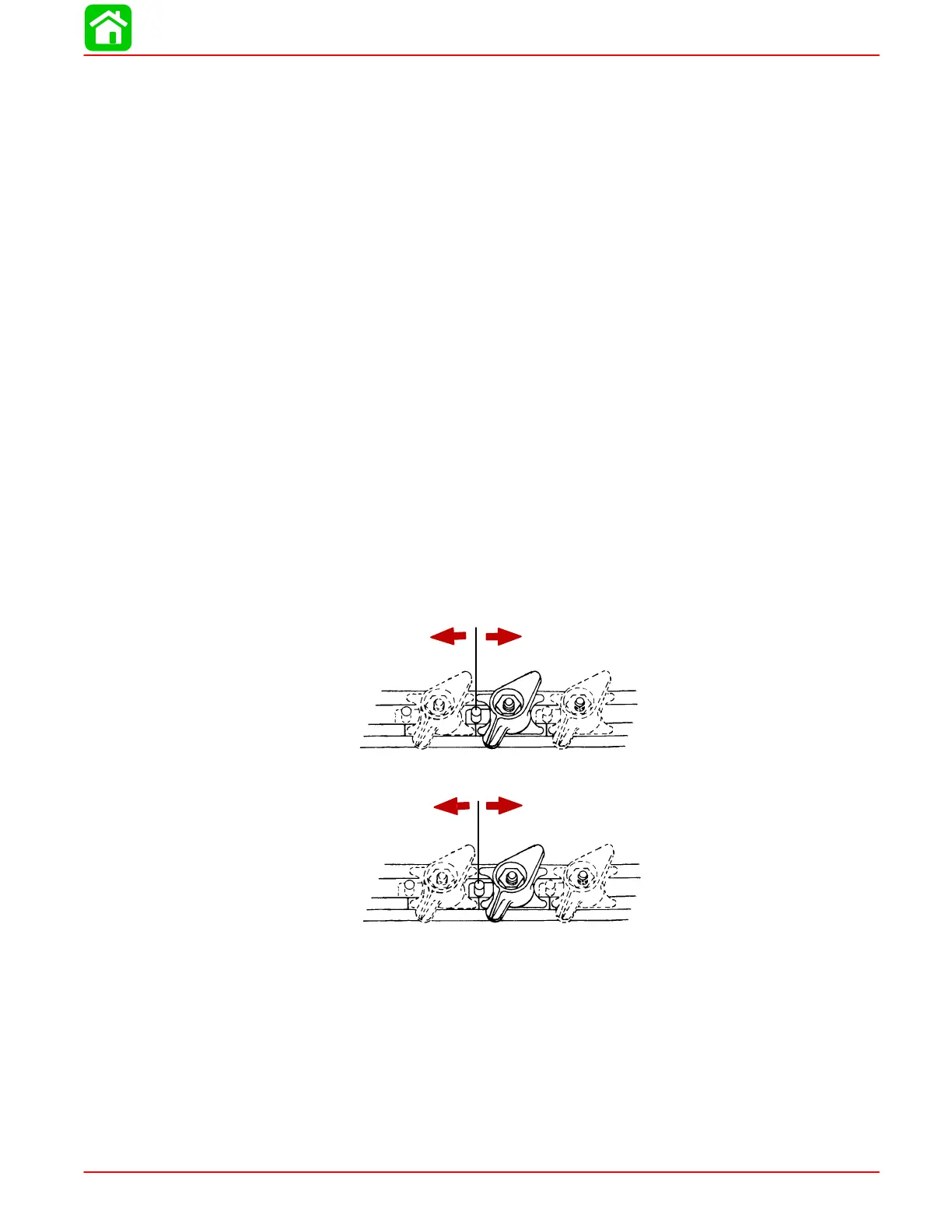
OUTBOARD SHIFTING DIRECTION
On counter rotation outboards, the shift linkage moves in the opposite direction compared
to a standard rotation outboard.
STANDARD ROTATION GEAR OUTBOARDS
Forward Gear
Reverse Gear
COUNTER ROTATION OUTBOARDS
Forward Gear
Reverse Gear
 Loading...

