WIRING DIAGRAMS
Page 2D-22 90-883728 JULY 2001
System Monitor V2.0
Basic Operation
The System Monitor is an LCD multi-function display gauge. A variety of displays can be
activated using the
button.
Pressing the
button scrolls the following displays: fuel used, tachometer (RPM), fuel
flow, power trim position, engine temp, water pressure, battery voltage, traveling range (if
calibrated), and water depth (if equipped with transducer).
The System Monitor will power up when the ignition is turned on.
The display includes a backlight which allows you to read it at night. The backlight bright-
ness is adjustable using
button.
In the event of a warning alarm, the warning icon(s)
will be displayed.
The System Monitor can be calibrated to display both the English or the Metric system. The
System Monitor can also be calibrated so that the trim position is displayed whenever the
propulsion unit is trimmed. Refer to
Cal1
Calibration Section for details.
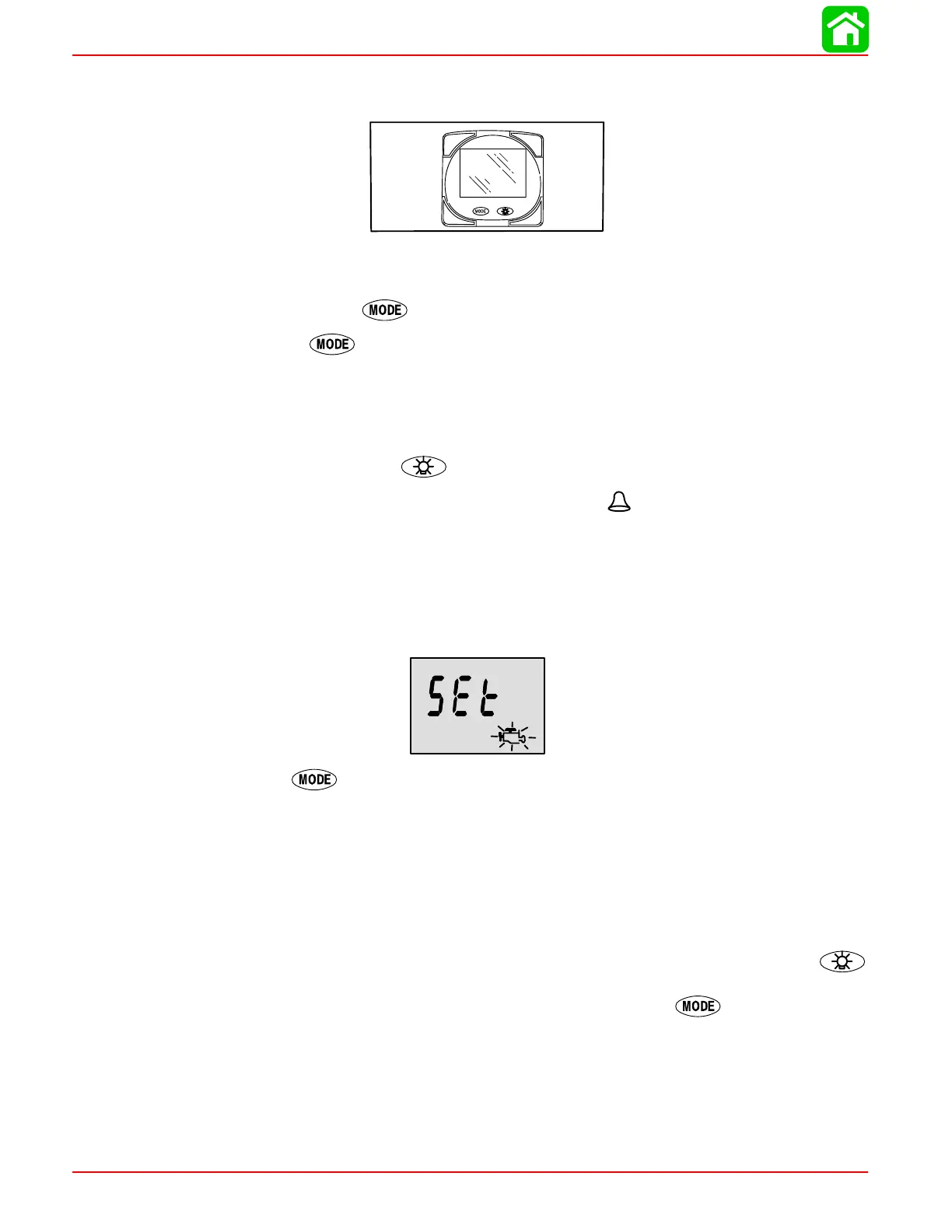
Initial Power Up (Or After Master Reset)
Unit will display software level then flash the word “SEt” in conjunction with engine icon.
Press the button.
The unit will begin it’s “Auto–detection” of engine type procedure. In this procedure System
Monitor checks with the engine control module (ECM) to see what type of engine you have
and presets the data monitoring screens accordingly, (e.g., If System Monitor detects an in-
board engine connected to the data network it will turn off all engine/drive TRIM functions as
these functions are not used in an inboard engine installation). The intention is to make initial
setup easier.
NOTE: If “2001” comes up during auto detect the gauge has detected that your engine
is a pre 2002 model. You will need to manually select your engine type. Use the
button to scroll through the choices. Stnd = Stern Drive, Inbd = Inboard, JEtd = Jet Drive,
Out2 = Outboard 2 Stroke, Out4 = Outboard 4 Stroke. Press
to continue.
 Loading...


