EasyManuals Logo
Home>Meyer Sound>Subwoofer>M1D

Meyer Sound M1D User Manual

Meyer Sound M1D
24 pages
To Next Page IconTo Next Page
To Previous Page IconTo Previous Page
Page #10 background imageLoading...
Page #10 background image
M1D Rigging Grids and Accessories
PN: 05.115.001.01 B
Page 10 of 24
Meyer Sound Laboratories Inc.
www.meyersound.com
T: +1 510 486.1166
F: +1 510 486.8356
M1D Rigging Grids and Accessories
PN: 05.115.001.01 B
Page 11 of 24
Meyer Sound Laboratories Inc.
www.meyersound.com
T: +1 510 486.1166
F: +1 510 486.8356
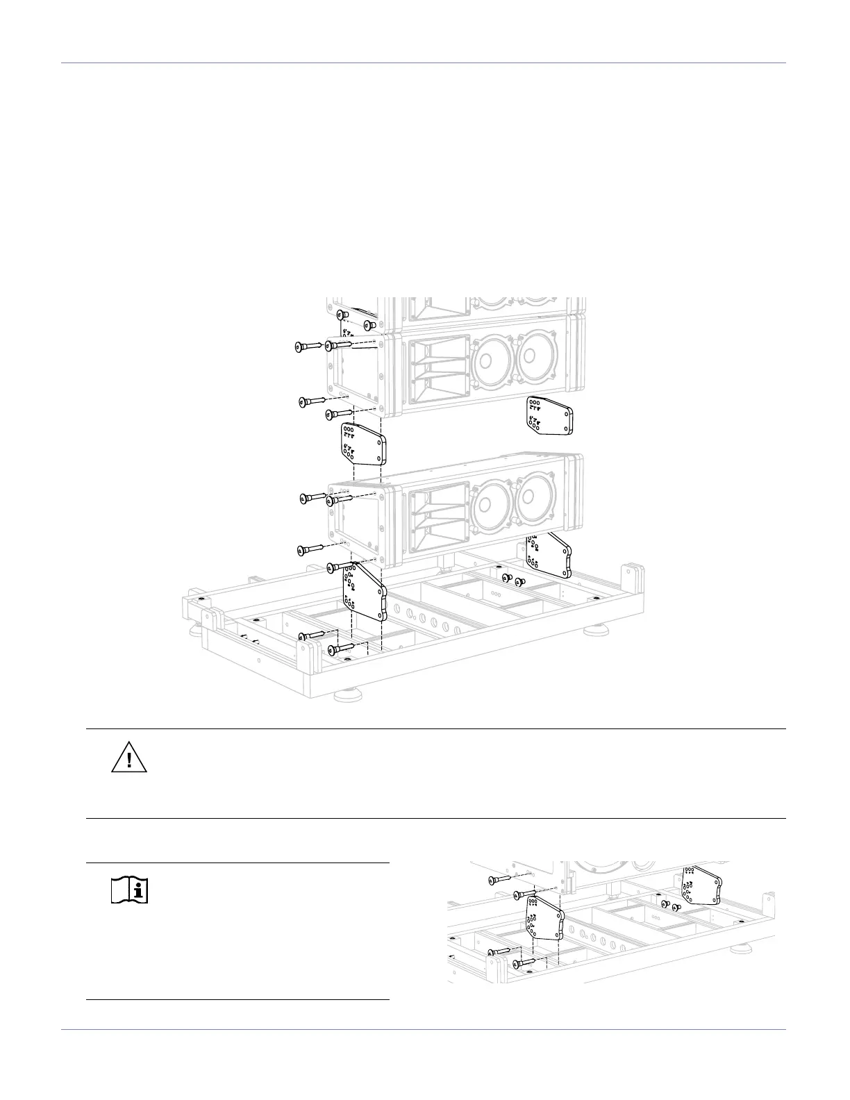
MG-1D GRID IN FORWARD GROUND STACKED CONFIGURATION
This conguration is used for ground stacking a predominantly up tilted M1D and/or M1D-Sub array. It provides from
-14° to +14° of tilt in 2-degree increments between the MG-1D multipurpose grid and the rst loudspeaker when using
an M1D as the rst element of the array. The grid’s extension frame (located to the rear of the array) can be deployed
to provide a larger footprint towards the rear for improved stability.
Install the M1D grid cam as shown into the MG-1D grid. Please note that the grid side of the M1D grid cam faces the
MG-1D grid. Secure all cams with the quick release pins (QRPs), then install the M1D at the pre-determined angle. The
M1D grid cam is only used in transition from the MG-1D grid to the rst M1D/M1D-Sub. After this is complete, use the
M1D links with the QRPs to complete the rest of your array as shown.
NOTE: If the rst element of the
array is an M1D-Sub, the M1D grid
cam needs be reversed (grid side facing
the M1D-Sub). In this case, down tilt
from 0° to -14° in 2-degree increments is
possible. Use M1D links to complete the
rest of the array.
CAUTION: When ground stacking an M1D/M1D-Sub array on an MG-1D multipurpose grid, always
keep the center of gravity within the footprint of the leveling feet. For extra stability, the footprint can be
enlarged by use of the extension frame. To further secure larger arrays, particularly in outdoor situations, use a
tie down or extra weight on the grid, or a safety system on the array.

Other manuals for Meyer Sound M1D

Questions and Answers:

Question and Answer IconNeed help?

Do you have a question about the Meyer Sound M1D and is the answer not in the manual?

Meyer Sound M1D Specifications

Acoustical IconAcoustical
operating frequency range32 Hz - 180 Hz
frequency response35 Hz - 160 Hz ±4 dB
phase response50 Hz - 120 Hz ±45°
maximum peak SPL130 dB
dynamic range>110 dB
Coverage IconCoverage
horizontal coverage360°
vertical coverageVaries, depending on array length and configuration
Transducers IconTransducers
low frequency transducerTwo 10" cone drivers with neodymium magnets
nominal impedance4 Ω
voice coil size2"
power-handling capability400 W (AES)
Audio Input IconAudio Input
input typeDifferential, electronically balanced
maximum common mode range±15 V DC
input impedance10 kΩ differential between pins 2 and 3
Amplifiers IconAmplifiers
amplifier typeTwo-channel complementary MOSFET output stages (class AB/bridged)
output power450 W total
THD, IM, TIM<.02 %
load capacity4 Ω each channel
AC Power IconAC Power
safety agency rated operating range100 - 240 V AC; 50/60 Hz
idle current0.41 A rms (115 V AC); 0.33 A rms (230 V AC); 0.42 A rms (100 V AC)
max long-term continuous current (>10 sec)3.2 A rms (115 V AC); 1.6 A rms (230 V AC); 3.7 A rms (100 V AC)
burst current (<1 sec)5.0 A rms (115 V AC); 2.5 A rms (230 V AC); 5.8 A rms (100 V AC)
ultimate short-term peak current draw17 A pk (115 V AC); 8.5 A pk (230 V AC); 20 A pk (100 V AC)
inrush current15 A pk (115 V AC); 13 A pk (230 V AC); 15 A pk (100 V AC)
Weight and Dimensions IconWeight and Dimensions
width22.62" (575 mm)
height13" (330 mm)
depth17.50" (445 mm)
weight70 lbs (31.75 kg)

Related product manuals