M1D Rigging Grids and Accessories
PN: 05.115.001.01 B
Page 6 of 24
Meyer Sound Laboratories Inc.
www.meyersound.com
T: +1 510 486.1166
F: +1 510 486.8356
M1D Rigging Grids and Accessories
PN: 05.115.001.01 B
Page 7 of 24
Meyer Sound Laboratories Inc.
www.meyersound.com
T: +1 510 486.1166
F: +1 510 486.8356
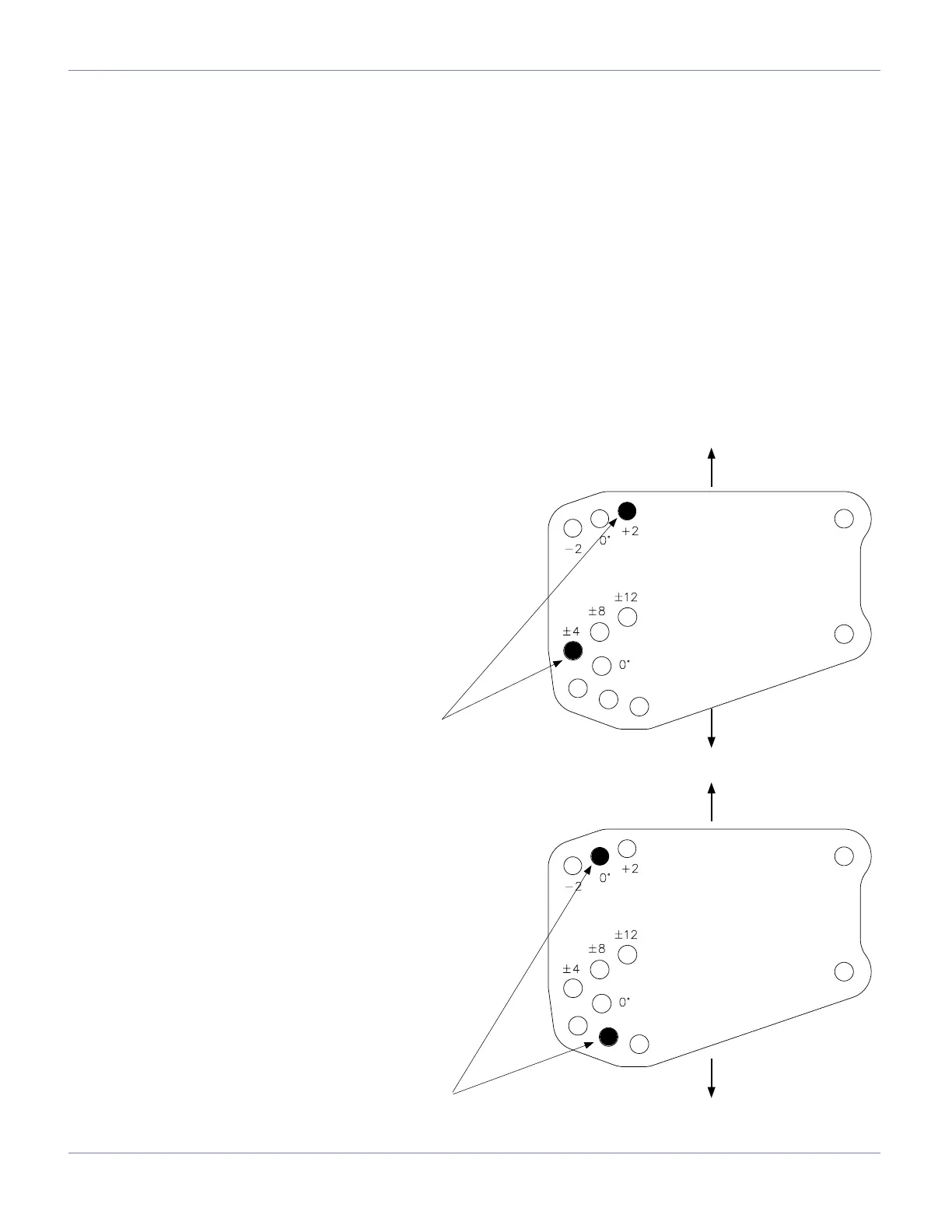
M1D GRID CAM OVERVIEW
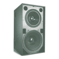
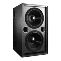
The M1D grid cams are used to connect an M1D/M1D-Sub to the MG-1D multipurpose grid or MTG-1D top grid. The
holes in the M1D grid cams align with holes in the MRF-1D rigging frame and the MG-1D grid. Two quick release pins
(QRPs) are provided per side that insert through the holes.
A variety of tilt angles can be achieved through the selection of pin positions. In a own array, positive angles are used
for up tilt and negative angles are used for down tilt with respect to the adjacent element above. For ground stack ar-
ray congurations, the angle is with respect to the adjacent element below.
The angle of the loudspeaker in relation to the grid is calculated by adding together the numbers etched next to
each hole. When an M1D is the rst unit in the array, the M1D grid cam provides from -14° to +14° of tilt in 2-degree
increments. If an M1D-Sub is used as the rst unit, 0° to +14° of tilt is possible, again in 2-degree increments.
Although own congurations may not require the exibility of the M1D grid cam, it should always be used as the rst
link between the grid and the array. In own congurations, the up and down tilt can additionally be adjusted using
chain motors, or differing lengths of steel or span set. In a ground supported situation, however, the M1D grid cam is
the only way to tilt the array up or down in relation to the MG-1D grid.
Example 1 (Flown)
Top grid cam pin position +2
Bottom grid cam pin position -4
Total angle -2° (down tilt)
Example 2
Top grid cam pin position 0
Bottom grid cam pin position +8
Total angle +8° (up tilt)
To Grid
Grid Side
QRP locations
To M1D loudspeaker
To Grid
Grid Side
To Grid
QRP locations
To M1D loudspeaker
To Grid
 Loading...