M1D Rigging Grids and Accessories
PN: 05.115.001.01 B
Page 12 of 24
Meyer Sound Laboratories Inc.
www.meyersound.com
T: +1 510 486.1166
F: +1 510 486.8356
M1D Rigging Grids and Accessories
PN: 05.115.001.01 B
Page 13 of 24
Meyer Sound Laboratories Inc.
www.meyersound.com
T: +1 510 486.1166
F: +1 510 486.8356
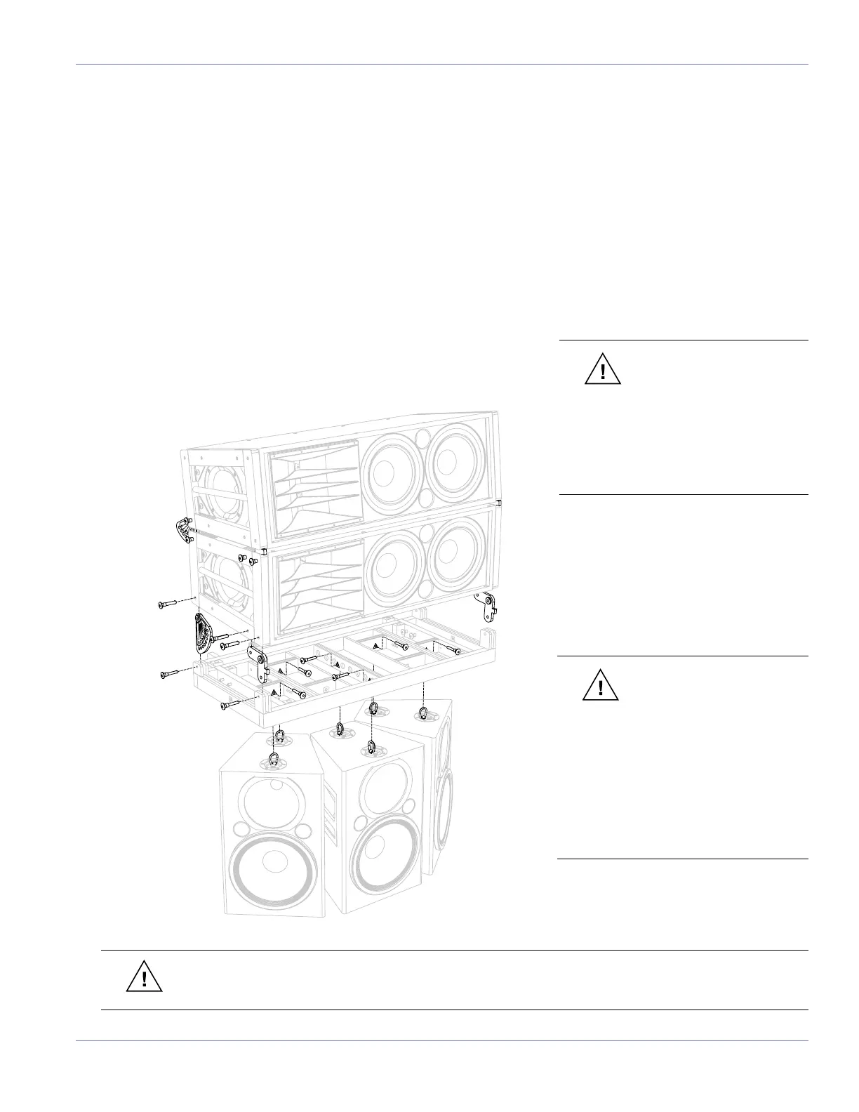
USING THE MG-1D GRID TO TRANSITION FROM M2D TO 3 UPA-2P LOUDSPEAKERS (40° SPLAY)
This conguration provides 0° to 7° of down tilt in 1-degree increments for a downll of UPA-2P compact narrow
coverage loudspeakers when transitioning from an M2D array. A total of 110 degrees of horizontal coverage is
provided by the UPA-2P array. The UPA-2Ps can also be own independently with the MG-1D grid from a single pick-
up point on the frame’s center bracket.
To assemble this conguration, lift the D-Rings on the UPA-2Ps and guide them into each hole marked with a triangle
on the MG-1D grid. Fasten by fully inserting the quick release pins (QRPs) into the appropriate holes in the grid while
securing the D-Rings. The MG-1D grid can then be attached to the M2D system using the M2D CamLinks, M2D front
links and M2D 5/16” QRPs.
Maximum Load:
Triangle-marked UPA-2P pick-up points.
7:1 safety factor: 2 rows of (3) UPA-2Ps
462 lbs (209.5 kg)
CAUTION: When using
an MG-1D multipurpose
grid as a top grid to y a UPA-
2P array, it must always be
supported by at least one pick-up
hole from the main frame’s center
bracket. The extension frame may
be used as a secondary pick-up
location for tilting the array or
spreading the load between two
points.
CAUTION: When ying an
MG-1D grid and UPA-2P
array beneath an M2D array,
include the weight of the grid and
the weight of the UPA-2P array in
your total weight calculations. Do
not exceed the weight rating of
the primary supporting grid.
WARNING: The leveling feet must always be detached from the MG-1D grid before ying a system.
Unscrew the entire assembly, including the threaded leg, and remove completely.
 Loading...