M1D Rigging Grids and Accessories
PN: 05.115.001.01 B
Page 12 of 24
Meyer Sound Laboratories Inc.
www.meyersound.com
T: +1 510 486.1166
F: +1 510 486.8356
M1D Rigging Grids and Accessories
PN: 05.115.001.01 B
Page 13 of 24
Meyer Sound Laboratories Inc.
www.meyersound.com
T: +1 510 486.1166
F: +1 510 486.8356
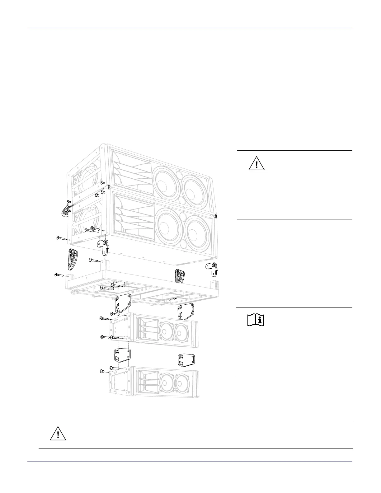
USING THE MG-1D GRID TO TRANSITION FROM M2D TO M1D ARRAYS
This conguration is used for applications that require the MG-1D grid to be used to transition from an M2D and
M2D-Sub array to a M1D and/or M1D-Sub array. It provides from 0° to -7° of tilt in 1-degree increments between the
M2D and the grid, and -14° to +14° of tilt in 2-degree increments between the MG-1D multipurpose grid and the rst
loudspeaker when using an M1D as the rst element of the array.
This gure below shows how the MG-1D grid can be congured to provide a transition from an M2D to an M1D
system. Note the orientation of the grid.
Install the M2D’s CamLink and front link into the cam and link positions on the MG-1D grid as shown. Securely fasten
using M2D 5/16" quick release pins, then attach the M1Ds and angle as desired.
CAUTION: When ying an
MG-1D grid and M1D array
beneath an M2D array, include the
weight of the grid and the weight
of the M1D array in your total
weight calculations. Do not exceed
the weight rating of the primary
supporting grid.
WARNING: The leveling feet must always be detached from the MG-1D grid before ying a system.
Unscrew the entire assembly, including the threaded leg, and remove completely.
NOTE: If the rst element of
the array is an M1D-Sub, the
M1D grid cam needs to be reversed
(grid side facing the M1D-Sub). In
this case, up tilt from 0° to +14° in
2-degree increments is possible.
Use M1D links to complete the rest
of the array.
 Loading...