EasyManuals Logo
Home>Meyer Sound>Subwoofer>M1D

Meyer Sound M1D User Manual

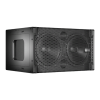
Meyer Sound M1D
24 pages
To Next Page IconTo Next Page
To Previous Page IconTo Previous Page
Page #14 background imageLoading...
Page #14 background image
M1D Rigging Grids and Accessories
PN: 05.115.001.01 B
Page 14 of 24
Meyer Sound Laboratories Inc.
www.meyersound.com
T: +1 510 486.1166
F: +1 510 486.8356
M1D Rigging Grids and Accessories
PN: 05.115.001.01 B
Page 15 of 24
Meyer Sound Laboratories Inc.
www.meyersound.com
T: +1 510 486.1166
F: +1 510 486.8356
USING THE MG-1D GRID TO TRANSITION FROM M2D TO A SINGLE UPA-1P LOUDSPEAKER
When transitioning from an M2D array, this conguration provides 0° to 7° of down tilt in 1° increments for a downll
comprised of a single UPA-1P compact wide coverage loudspeaker. The UPA-1P provides a total of 100° of horizontal
coverage. The UPA-1P can also be own independently with the MG-1D grid from a single pick-up point on the
frame’s center bracket.
To assemble this conguration, lift the D-Rings on the UPA-1P and guide them into each hole marked with a triangle
on the MG-1D grid. Fasten by fully inserting the quick release pins (QRPs) into the appropriate holes in the grid while
securing the D-Rings. The MG-1D grid can then be attached to the M2D system using the M2D CamLinks, M2D front
links and M2D 5/16” QRPs.
Maximum Load:
Triangle-marked UPA pick-up points.
7:1 safety factor: 2 rows of (1) UPA-1Ps
154 lbs (70 kg)
CAUTION: When using the
MG-1D grid as a top grid
to y a UPA-1P, it must always be
supported by at least one pick-up
hole from the main frame’s center
bracket. The extension frame may
be used as a secondary pick-up
location for tilting the array or
spreading the load between two
points.
CAUTION: When ying an
MG-1D grid and a UPA-1P
beneath an M2D array, include
the weight of the grid and the
weight of the UPA-1P in your total
weight calculations. Do not exceed
the weight rating of the primary
supporting grid.
WARNING: The leveling feet must always be detached from the MG-1D grid before ying a system.
Unscrew the entire assembly, including the threaded leg, and remove completely.
Other manuals for Meyer Sound M1D

Questions and Answers:

Question and Answer IconNeed help?

Do you have a question about the Meyer Sound M1D and is the answer not in the manual?

Meyer Sound M1D Specifications

Acoustical IconAcoustical
operating frequency range32 Hz - 180 Hz
frequency response35 Hz - 160 Hz ±4 dB
phase response50 Hz - 120 Hz ±45°
maximum peak SPL130 dB
dynamic range>110 dB
Coverage IconCoverage
horizontal coverage360°
vertical coverageVaries, depending on array length and configuration
Transducers IconTransducers
low frequency transducerTwo 10" cone drivers with neodymium magnets
nominal impedance4 Ω
voice coil size2"
power-handling capability400 W (AES)
Audio Input IconAudio Input
input typeDifferential, electronically balanced
maximum common mode range±15 V DC
input impedance10 kΩ differential between pins 2 and 3
Amplifiers IconAmplifiers
amplifier typeTwo-channel complementary MOSFET output stages (class AB/bridged)
output power450 W total
THD, IM, TIM<.02 %
load capacity4 Ω each channel
AC Power IconAC Power
safety agency rated operating range100 - 240 V AC; 50/60 Hz
idle current0.41 A rms (115 V AC); 0.33 A rms (230 V AC); 0.42 A rms (100 V AC)
max long-term continuous current (>10 sec)3.2 A rms (115 V AC); 1.6 A rms (230 V AC); 3.7 A rms (100 V AC)
burst current (<1 sec)5.0 A rms (115 V AC); 2.5 A rms (230 V AC); 5.8 A rms (100 V AC)
ultimate short-term peak current draw17 A pk (115 V AC); 8.5 A pk (230 V AC); 20 A pk (100 V AC)
inrush current15 A pk (115 V AC); 13 A pk (230 V AC); 15 A pk (100 V AC)
Weight and Dimensions IconWeight and Dimensions
width22.62" (575 mm)
height13" (330 mm)
depth17.50" (445 mm)
weight70 lbs (31.75 kg)

Related product manuals