M1D Rigging Grids and Accessories
PN: 05.115.001.01 B
Page 20 of 24
Meyer Sound Laboratories Inc.
www.meyersound.com
T: +1 510 486.1166
F: +1 510 486.8356
M1D Rigging Grids and Accessories
PN: 05.115.001.01 B
Page 21 of 24
Meyer Sound Laboratories Inc.
www.meyersound.com
T: +1 510 486.1166
F: +1 510 486.8356
4. MUB-1D MULTIPURPOSE U-BRACKET
The MUB-1D multipurpose U-bracket is mainly designed to support and aim a single M1D ultra-compact curvilinear
array loudspeaker in a oor or ceiling mounted conguration. However, it is robust and versatile enough for ying small
arrays of M1D loudspeakers. Multiple mounting holes provide maximum exibility.
The MUB-1D U-bracket does not have the strength or functionality of a rigging grid and therefore it is NOT
recommended for the following applications:
- If the array’s length and the angles between the cabinets force its center of gravity to fall outside the footprint of
the MUB-1D.
- If the array includes M1D-Subs.
- If the array requires up or down tilt using chain motors.
- If the array exceeds the load rating of the MUB-1D.
For these and other own applications that require a rigging grid, the MTG-1D or the MG-1D should be used.
For ground stacked arrays that require a support grid, or when a transition from an M2D and M2D-Sub array to a M1D
array is needed, the MG-1D grid should be used.
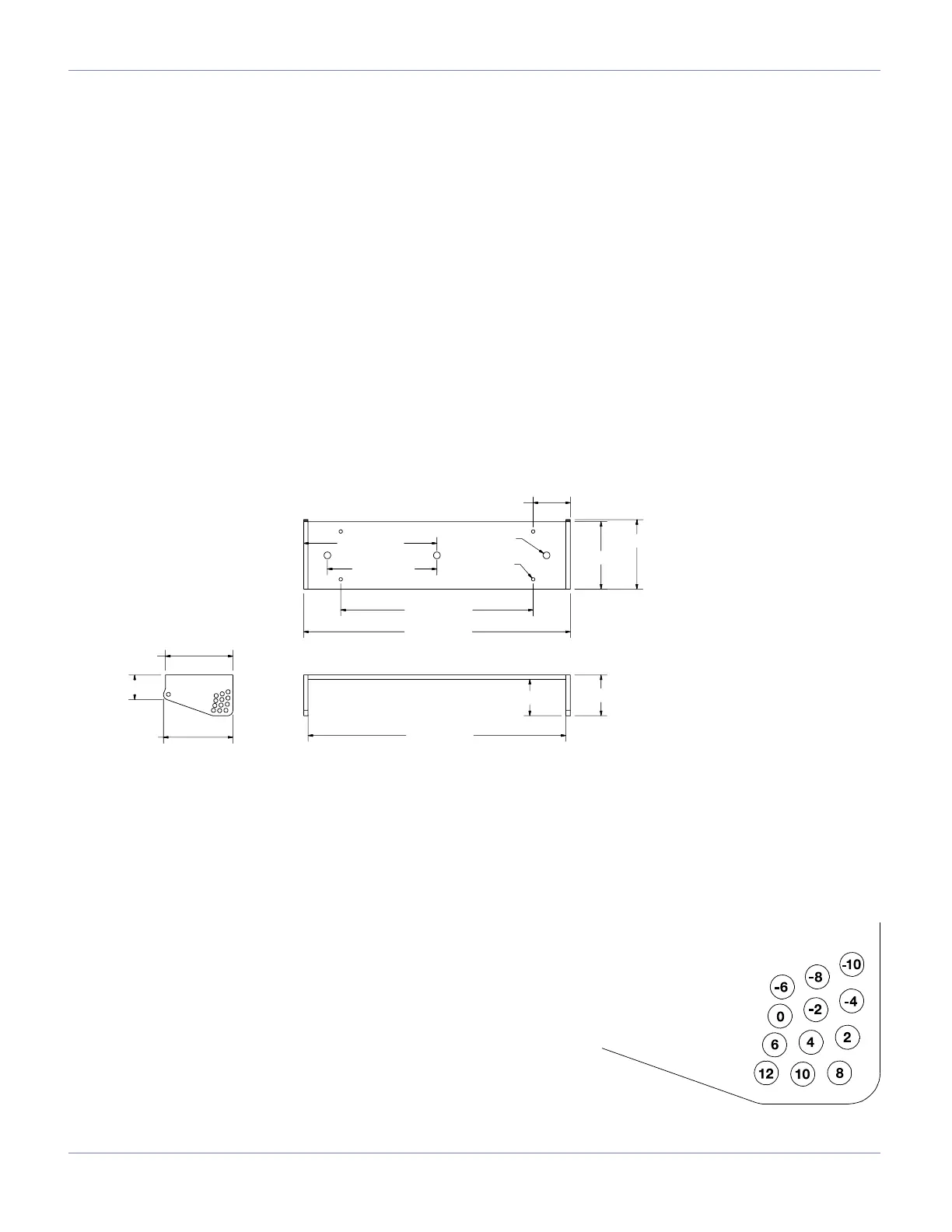
MUB-1D Multipurpose U-Bracket Dimensions:
MUB-1D Multipurpose U-Bracket Weight: 7 lbs (3.18 kg)
ANGLE SETTING
A number of holes are provided on each end of the MUB-1D
multipurpose U-bracket to facilitate angle setting. The holes align with
those in the MRF-1D rigging frame on the M1D. Two quick release pins
— provided with the M1D loudspeakers — per side are used to mount
the M1D to the MUB-1D U-bracket.
A variety of tilt angles are available through the selection of pin positions.
The diagram below shows the angles that can be achieved with relation
to the MUB-1D’s mounting plane. In ceiling-mounted or own arrays,
positive angles are used for up tilt and negative angles are used for down
tilt. For oor mounted congurations, positive angles are used for down
tilt. The MUB-1D U-bracket provides from +10° to -12° of tilt in 2-degree
increments.
MUB-1D Multipurpose U-Bracket
QRP Positions
 Loading...