M1D Rigging Grids and Accessories
PN: 05.115.001.01 B
Page 8 of 24
Meyer Sound Laboratories Inc.
www.meyersound.com
T: +1 510 486.1166
F: +1 510 486.8356
M1D Rigging Grids and Accessories
PN: 05.115.001.01 B
Page 9 of 24
Meyer Sound Laboratories Inc.
www.meyersound.com
T: +1 510 486.1166
F: +1 510 486.8356
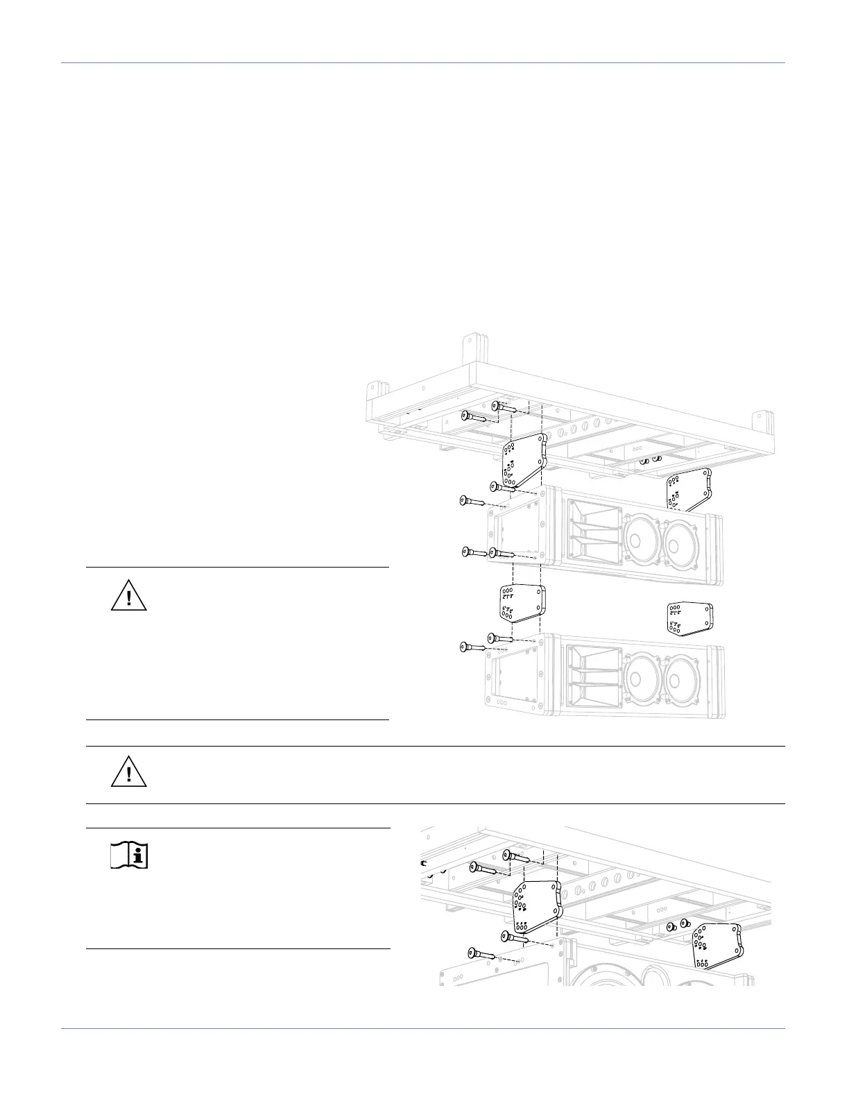
MG-1D GRID IN FORWARD FLOWN CONFIGURATION
“Forward Flown” dilineates that the MG-1D multipurpose grid is oriented with its integral sliding extension frame to the
rear. This is the most common conguration for ying an M1D and/or M1D-Sub array. It provides from -14° to +14° of
tilt in 2-degree increments between the grid and the rst loudspeaker when using an M1D as the rst element of the
array. If more tilt is required, the grid may also be tilted up or down by using single or multiple rigging points. If further
down tilt is needed, this can be achieved using the grid’s extension frame in the extended position.
Install the M1D grid cam as shown into the MG-1D grid, with the grid side of the M1D grid cam facing the MG-1D
grid. Secure all M1D grid cams with the quick release pins (QRPs), then install the M1D at the predetermined angle
(see page 5 for more information on setting tilt angles). The M1D grid cam is only used in transition from the MG-1D
multipurpose grid to the rst M1D/M1D-Sub. After this is complete, use the M1D links with the QRPs to complete the
rest of the array as shown.
CAUTION: When ying an array
from the MG-1D multipurpose grid,
it must always be supported by at least
one pick-up hole from the main frame’s
center bracket. The extension frame may
be used as a secondary pick-up location
for tilting the array or spreading the load
between two points.
WARNING: The leveling feet must always be detached from the MG-1D multipurpose grid before ying
a system. Unscrew the entire assembly, including the threaded leg, and remove completely.
Maximum Load:
7:1 safety factor: Up to 16 M1Ds or the
equivalent weight of M1Ds and/or M1D-
Subs or other products specied for
use with this grid. (496 lbs, 225 kg)
5:1 safety factor: Up to 22 M1Ds or the
equivalent weight of M1Ds and/or M1D-
Subs or other products specied for
use with this grid. (682 lbs, 309.2 kg)
NOTE: If the rst element of the
array is an M1D-Sub, the M1D grid
cam needs to be reversed (grid side facing
the Sub). In this case, up tilt from 0° to
+14° increments is possible. Use M1D links
to complete the rest of the array.
 Loading...