Hydraulic Connection MCAC-TSM-2008-02
68 Installation
4. Hydraulic Connection
The choice and installation of components is the responsibility of the installer who should follow good
working practice and current legislation. Before connecting the pipes, make sure they do not contain stones,
sand, rust, dross or other foreign bodies which might damage the unit. Construction of a bypass is
recommended to enable the pipes to be washed through without having to disconnect the unit (see drain
valves). The connection piping should be supported in such a way as to avoid it weighing on the unit. It is
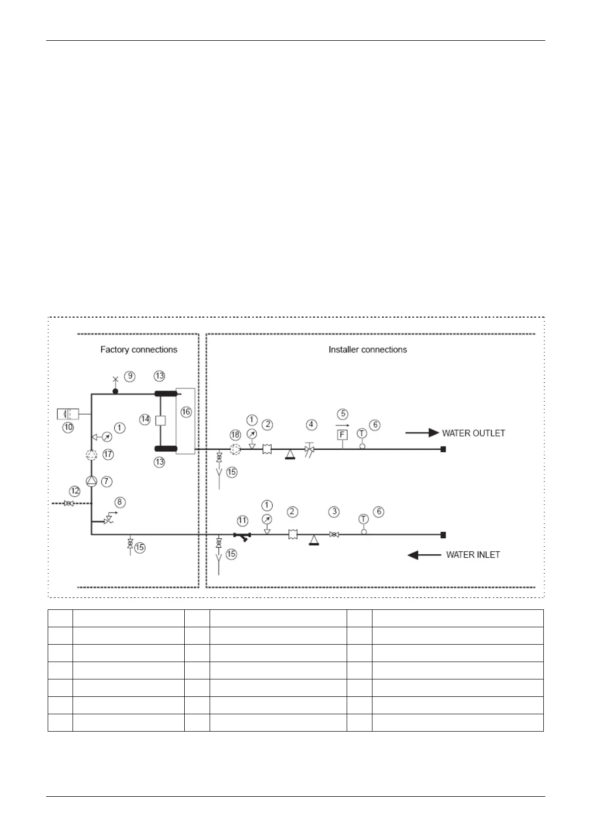
recommended that the following devices are installed in the water circuit of the evaporator:
1. Two pressure gauges with a suitable (inlet and outlet)
2. Two vibration damper joints (inlet and outlet)
3. Two gate valves (normal inlet and calibrating in outlet)
4. A flow switch (inlet) or a differential pressure switch (inlet-outlet).
5. Two thermometers (inlet and outlet).
6. An inlet filter as close as possible to the evaporator and positioned to allow easy access for routine
maintenance.
7. An energy-saving water tank.
8. Additional pump.
9. The connecting line of flow switch, which mounted outside the unit, should be connected in series with
the pressure-difference
No Name No Name No Name
1 Pressure gauge 7 Pump 13 Temperature sensor
2 Vibration damper joint 8 Safety valve 14 Differential pressure switch
3 Gate valve 9 Air vent 15 Drain/chemical washing valve
4 Calibrating valve 10 Expansion tank 16 Plate heat exchanger
5 Flow switch 11 Mesh filter 17 Additional pump
6 Thermometer 12 Auto-water replenishing 18 Additional pump
If the installation requires a useful head higher than that obtained by installing a pump assembly and storage
tank, it is recommended that an additional pump is installed on the unit. Provided the additional pump
installed inside of unit (only model 12/14/16kW can be installed inside of unit), the pump must connected
 Loading...