Hydraulic Connection MCAC-TSM-2008-02
70 Installation
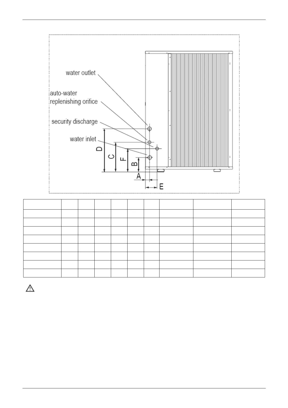
Size and position of connections
Model
A
(mm)
B
(mm)
C
(mm)
D
(mm)
E
(mm)
F
(mm)
Water
inlet/outlet (Ø)
Auto-water
replenishing (Ø)
Security
discharge (Ø)
MGC-F05W/N1 70 118 196 328 122 170 R1 G1/2 G1/2
MGC-F07W/N1 70 118 196 328 122 170 R1 G1/2 G1/2
MGC-F09W/N1 76 107 217 305 145 107 R5/4 G1/2 G1/2
MGC-F10W/N1 76 107 217 305 145 107 R5/4 G1/2 G1/2
MGC-F10W/SN1 76 107 217 305 145 107 R5/4 G1/2 G1/2
MGC-F12W/SN1 78 84 174 297 148 148 R5/4 G1/2 G1/2
MGC-F14W/SN1 78 84 174 297 148 148 R5/4 G1/2 G1/2
MGC-F16W/SN1 78 84 174 297 148 148 R5/4 G1/2 G1/2
Important
a) The installation must be filled to a pressure of between 1 and 2 bars.
b) It is recommended that this operation be repeated after the unit has been operating for a number of
hours. The pressure of the installation should be checked regularly and if it drops below 1 bar, the water
content should be topped-up.
c) Check the hydraulic tightness of joints.
d) If the fluid in the circuit contains anti-freeze, it should not be allowed to drain freely as it is pollutant.
e) It should be collected for possible reuse.
f) When draining after heat pump operation, take care as the water may be hot (up to 50℃).
 Loading...