MCAC-TSM-2008-02 Checking and Starting Up the Unit
Installation 75
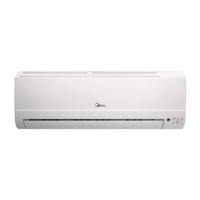
- Use grommet A for the electrical power cable and grommet B for the other external wires.
- Replace the inspection panel.
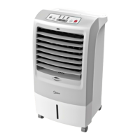
- Position the main switch QF1 (outside the unit) in the “ON” position.
- The “POWER” LED on the control panel “ST542” comes on to signal that voltage is present.
6.3 Activating and deactivating the unit
-Set the remote keyboard “A6” (if present) to ON.
- To ACTIVATE and DEACTIVATE the COOLING and HEATING functions, use the "ST542" control panel or
the remote keyboard "A6" if present.
During this phase, if the following indications appear on the display, follow the instructions:
Important
- E20 check water flow rate and differential pressure switch.
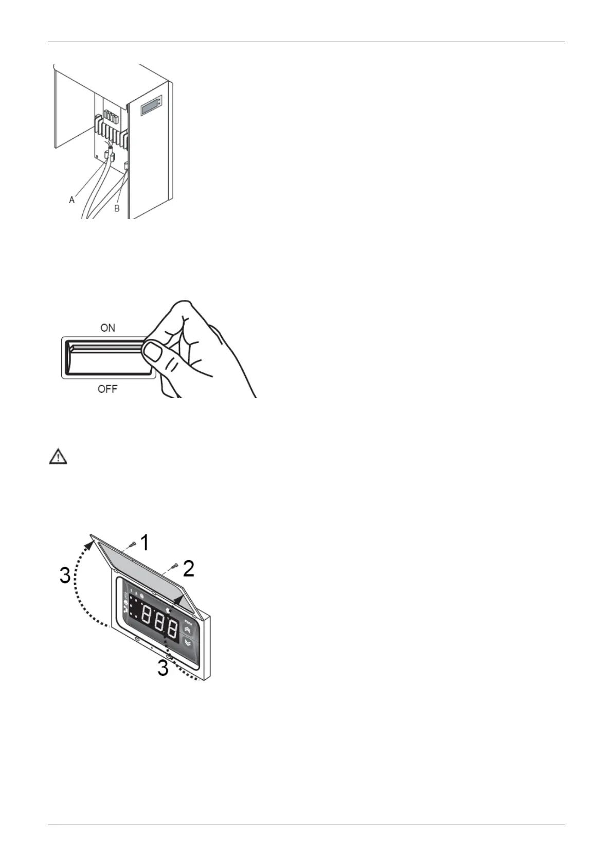
To access the control panel, open the door:
- remove the screw 1 and screw 2;
- lift t he door 3.
 Loading...