10
2.7 VALVES
Back Pressure Valves
All metering pumps are prone to overpumping (excessive output) at low discharge pressures. To prevent this condition
from occurring, it is necessary to maintain approximately 10 psi (0.7 bar) back pressure against the pump. This can
be accomplished through the installation of a back pressure valve in the discharge line. Typically, the valve should be
located near the pump. However, back pressure valves for large pumps with long and extremely small discharge lines
may have to be installed near the point of discharge into the process (to minimize siphoning tendencies).
Pulsation Dampeners
An accumulator, surge chamber, surge suppressor, or pulsation dampener should be used with the back
pressure valve in the discharge line to absorb the ow peaks between the pump and the back pressure valve.
Without the pulsation dampener the valve mechanism will snap open and closed with the surge from each
pump stroke. The pulsation dampener will allow the back pressure valve to oscillate about a partly-closed
position, thus minimizing wear on the valve. Discharge line pulsation dampeners offer the further advantage of
limiting the ow and pressure variations characteristic of this kind of pump. Installing a properly sized pulsation
dampener will improve pump performance and may reduce system costs dramatically by permitting the
substitution of smaller piping. Please contact your dealer for further information on pulsation dampeners.
Safety Valves and Priming Valves
Motor-driven positive displacement pumps can develop excessive discharge pressure long before thermal overload
devices interrupt the motor electrical circuit. To prevent a blocked discharge line from causing damage to the pump,
piping, or process equipment, install a safety valve in the pump discharge line. This valve is designed and sized to
handle system ow rates and pressures safely while resisting corrosion by the process liquid.
To aid in pump start-up, it is advisable to install a priming valve on the discharge side of the liquid end.
Shut-off Valves
Provide shut-off valves in both suction and discharge lines next to the pump. Locate discharge line shut-off valve
downstream from the inlet connection of the safety valve. Figure 2-3 shows recommended valve locations.
2.8 ELECTRICAL CONNECTIONS
OPERATION WITH THE WRONG MOTOR ROTATION MAY DAMAGE THE PUMP AND MOTOR AND
VOID THE WARRANTY.
DO NOT FORGET TO CONNECT THE EARTH TERMINAL ON THE MOTOR TO THE EQUIPMENT
EARTH CONDUCTOR.
Ensure that the electrical supply matches the pump motor nameplate characteristics. Connect the motor in
accordance with the instructions and connection diagrams on the motor (or in the motor terminal box).
Note:
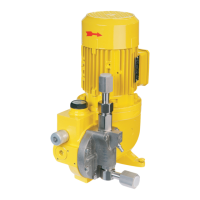
Before operating the pump, check the direction of rotation of the motor to be sure it matches the direction of
the arrow on the motor fan cover (rotation should be clockwise when viewed from the top of the motor).
The electrical protection installed for the motor (fuse or thermal protection) must be suitable for the motor's rated
current.
CAUTION

 Loading...


