34
A
PPLICATIONS AND APPLICATION INTERFACES
CHAPTER 2 SYSTEM OVERVIEW
Download documents, system software and tools
Before you start, download the documents and applications from the proprietary Mitel sites.
Proceed as follows to organize all downloads in a common folder:
1.
Download the Documentation set from the Mitel document portal [1]
2. If your Mitel SMB Controller does not have internet access, download the latest MiVoice Office 400
application software (e.g. “mivo400-8923a0-r3.lib32_aarch64_ilp32.rpm”) and the SMB Controller
system software (e.g. “Mitel-SMBC_Management-1.1.9.1_Helium.zip”) from [2] into the folder
named Mitel.
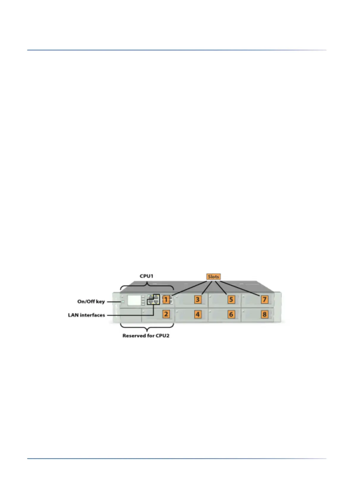
Equip, connect and power on
The communication server ships with a plugged-in processor card (CPU1) containing some interfaces
and is ready to use as a basic system.
CAUTION:
• Before you begin, read the product information and safety instructions carefully (see the PDF
included in the Documentation set or the printed sheet included in the delivery package).
• To prevent ESD damage to the components, always touch the earthed metal case of the communi-
cation server before carrying out work inside the housing. This also applies to handling interface
cards, proces-sor cards, and system modules that are not packed inside the ESD protective wrap-
ping.
1. Ensure that the communication server is disconnected from the power supply.
2. Insert interface cards (if any) starting with slot 3 and tighten the screw on them on. Leave slot 2
empty.
3. Install system modules (DSP modules or an EIP module) if any:
– Remove the CPU1 card.
– Mount the system modules on the CPU1 card.
– Insert the CPU1 card back in slot 1 and tighten the screw.
4.
Connect the LAN cable to one of the LAN interfaces on the front panel.
5. Set the voltage converter on the rear panel to the voltage of the available mains power (230 VAC or
115 VAC).
CAUTION: Printed circuit boards may be damaged or become defective if the communication server
is operated at a voltage different from that set on the voltage selector.

 Loading...